- Semiconductor BusinessHOME
- Products and Services of Macnica,Inc.
-
technical information

-
Events and Seminars
- Handling Manufacturer
- Support
- Inquiry
- Click here to purchase products
- Semiconductor business e-mail magazine registration


 Narrow down by specifying conditions
現在2256件がヒットしています。check


Introduction
It's "Poki".
Creating a board that allows you to make your desired operation using FPGA in production practice,
I made a circuit.
When the circuit board was completed,
From my senior, "Whether the configuration has been completed successfully and entered the user mode
Have you checked with an oscilloscope? "They said.
This time, Intel's configuration dedicated ROM "EPCS16" is used.
When using EPCS16, it is in Active Serial (hereafter AS) configuration mode.
Certainly, when doing AS configuration, like JTAG configuration
Quartus® II on PC does not show success or failure,
The only way to know if the configuration was successful is if the user circuit is working.
By the way, about the configuration mode, seniors wrote an article in the past, so please use it.
So I decided to look for a signal that could confirm that the configuration was successful.
Which pin should I look at?
There are many configuration related pins.
Figure 1 is a timing chart for AS configuration.
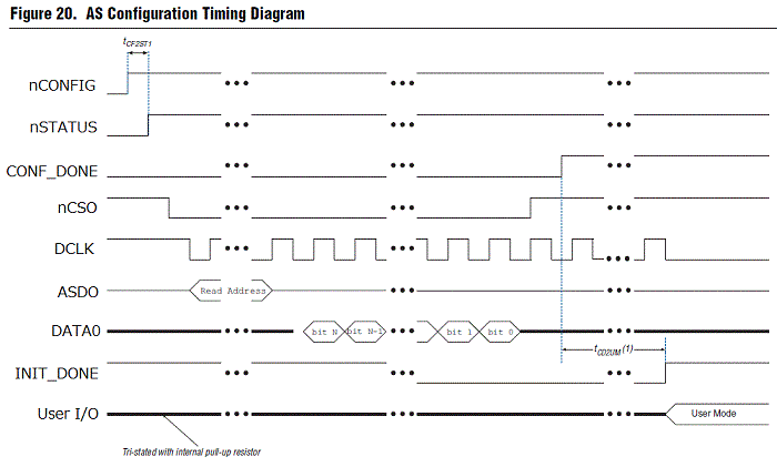
(Source: Serial Configuration (EPCS) Devices Datasheet)
There are two FPGA pins that indicate completion of configuration.
CONF_DONE : When all configuration data has been received without error,
Signal going low -> high (external pull-up)
INIT_DONE : Complete receiving all configuration data and initialize
Signal that goes high (external pull-up) when user mode is entered after completion
This time I decided to take a look at the INIT_DONE pin, which I never used.
The behavior of the INIT_DONE pin during configuration is as follows:
“High” at power on → “Low” during configuration
→ Initialization completed ” High ”
that? Where is it?
This INIT_DONE pin is treated as an Option, so first enable this pin.
To enable the INIT_DONE pin from the Quartus II menu
Assignments → Device… → Device & Pin Options… in Category under General
Check Enable INIT_DONE output.

When I enabled the INIT_DONE pin and tried to do the pin placement for INIT_DONE on the Pin Planner...
that? No INIT_DONE pin! !

In addition, nCS0, DCLK, ASD0, and DATA0 in Figure 1 are also absent.
So I decided to ask my seniors for help.
pre-determined signal
Poki "Senpai, I can't see configuration pins on the Pin Planner.
How do I pinout? ”
Senpai: nCS0, DCLK, ASD0, DATA0 and INIT_DONE
Since it is a signal that is originally decided which pin on the device to use, there is no need to arrange the pin. ”
Poki : Does that mean it won't appear on the Pin Planner?
Senior: “No, it will be displayed by doing Back-Annotate Assignments.”
Back-Annotate Assignments
Back-Annotate Assignments at compile time
It reflects the information such as pin assignment automatically set by Intel® Quartus® Prime to your settings.
How to do it is Quartus II menu Assignments → Back-Annotate Assignments… after compiling
Just make sure Pin & Device assignments is checked and press OK.
This is reflected.

Looking at the Pin Planner...

The information of the dedicated pin whose arrangement has been decided has appeared!
This is safe ♪
When I think about it, I get advice from my seniors.
Notes and pin information for Back-Annotate assignment
Senior: But when Back-Annotate Assignments is executed, user I/O pins that have not been pin-assigned are automatically set to arbitrary pins, so
Set the pins whose pin layout has been decided first. ”
User I/O pins in your design should be pin-outed according to the board you created.
If you don't do this pinout yourself, Intel® Quartus® Prime will place the pins at compile time without any relation to the board information, so be careful.
Senpai: Also, the information about the dedicated pins whose placement was originally decided is written in the pinout file of the device, so
Let's look at that and then place the user I/O pins. ”
You can download a pinout file with pin information for your device from Intel's website.
"Pinout Files for Intel® FPGA Devices"
If you place a user I/O pin on a dedicated pin that has a fixed placement, the following error will occur.
(I deleted the pinout information of PIN_98 which is the pin of INIT_DONE and forced to place other pins.)

You can avoid this error by avoiding such dedicated pins at the board design stage.
Waveform confirmation with an oscilloscope
Now that I know which pin the NIT_DONE pin is assigned to, I put in a pull-up resistor and looked at the waveforms during AS configuration.

You can see the “High” → “Low” → “High” behavior during configuration of the INIT_DONE pin.
You can see that the AS configuration was successful and you are now in user mode.
We now know that the AS configuration is complete.
Today's POINT
・Check dedicated pins in the pinout file before placing user pins.
・Dedicated pins related to configurationare displayed on thePin PlannerbyBack-Annotate Assignments after compiling.
・Back-Annotate Assignments are performed after placing user pins, because Quartus IIautomatically placespins that are not pin-placed during compilation.