- Semiconductor BusinessHOME
- Products and Services of Macnica,Inc.
-
technical information

-
Events and Seminars
- Handling Manufacturer
- Support
- Inquiry
- Click here to purchase products
- Semiconductor business e-mail magazine registration


 Narrow down by specifying conditions
現在2240件がヒットしています。check


Since it was decided to configure in AS mode last time, the next step is to select the ROM.
Altera's configuration ROM used in AS mode configuration is the EPCS series.
Even if it's a configuration ROM, doesn't the capacity change depending on the size of the design? I thought, how do I decide the size of the EPCS when I may add more designs later...
For the time being, I confirmed the number of Total Logic Elements from the compilation report, but I didn't know how many Mbits of EPCS I should use.
Well what happened...
When I asked a senior, I was told that the size of the configuration ROM depends on the device, not the design. So, even if you make a 1-bit counter or a more complicated clock than a counter, will the ROM capacity remain the same? I'm confused.
...and go back to the basics.
I thought I should know the structure of the device first. Inside the device, you can see that the Logic Elements are arranged in a grid pattern.
In addition, you can see that the Cyclone® IV E device used this time has a multiplier block and a memory block called M9K arranged vertically. There are PLLs on the four corners of the device.
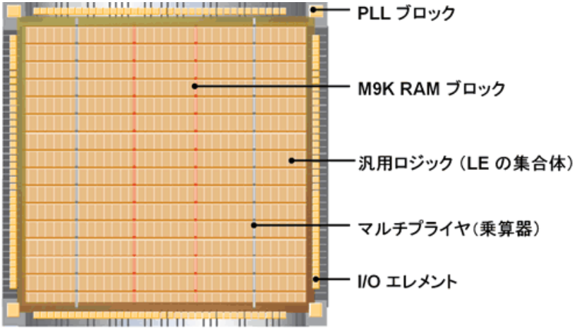
We did not use 100% of the Cyclone® IV E device's resources to implement the clock function.
The fact that the configuration ROM is determined for the device scale even though 100% of the resources are not used means that all the used/unused information for each resource is written.
The FPGA is composed of transistors, and it seems that circuits are realized by ON / OFF settings for gate connections and wiring switches.
The configuration ROM capacity depends on the device because information on all transistors that make up the device is required regardless of whether or not it is used.
So how much capacity does the EP4CE10 on the board need?
There was a list in Section III → Configuration File Size of the handbook! The figure below shows the list.
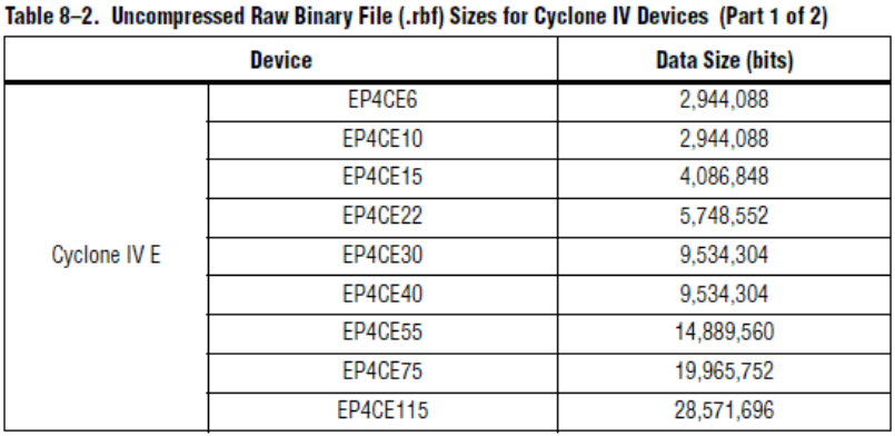
The table above summarizes the rbf file sizes.
An rbf file is an abbreviation for Raw Binary File, and is a file that contains only data without header or footer information.
Since it is a data-only file, it is also used for estimating the configuration ROM.
From the table above, we can see that the EP4CE10 requires roughly 3 Mbits of capacity.
So, what are the EPCS capacities?
This was also listed in the EPCS handbook. Below is a list of EPCS.
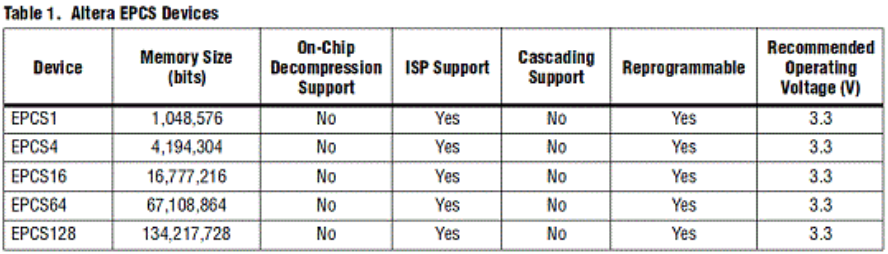
From the above table, if it is EPCS4, it seems that the configuration data of the device will be included.
However, in reality, I felt that EPCS4 was a waste even though it was about 3 Mbits. So, when I read the Cyclone® IV handbook, there was a mention that the configuration data can be compressed.
If it can be compressed, the capacity of EPCS may be reduced by one size. If you do that, you will succeed in reducing the cost of the board!
As for the compression ratio, it seems that 35% to 55% compression is possible.
The compression ratio of configuration data is design dependent.
Because it depends on the design, you can't know unless you generate the file with the compression option enabled.
In parallel with the design of the board, the design cannot proceed without knowing the size of the configuration ROM until the design is completed.
Therefore, the reference value is described in the handbook.
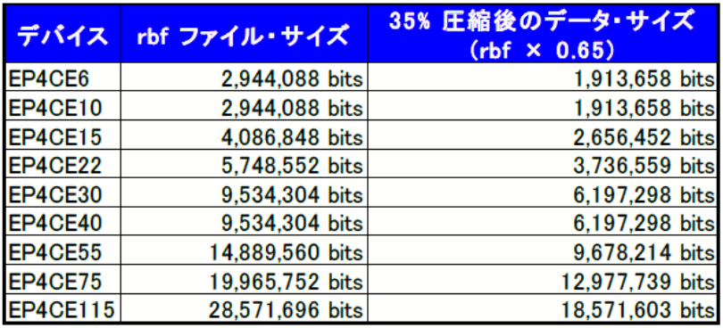
There is no problem if you calculate with the minimum value of the standard value, so when I calculated the configuration data with 35% of the minimum value, it was about 2 Mbit...
I'm sorry! It just barely fit into the EPCS1. If you look closely at the handbook, there is a note that EPCS1 cannot be used with Cyclone® IV.
Since EPCS4 is the minimum capacity, we decided to use EPCS4 and made an in-house order.
Also, here is a table with 35% compression applied to rbf for Cyclone IV E devices.
By the way, how long will it take to start up when configuration can be done in AS mode?
Next time, we will study about the time required for configuration.