- Semiconductor BusinessHOME
- Products and Services of Macnica,Inc.
-
technical information

-
Events and Seminars
- Handling Manufacturer
- Support
- Inquiry
- Click here to purchase products
- Semiconductor business e-mail magazine registration


 Narrow down by specifying conditions
現在2247件がヒットしています。check



Nice to meet you, my name is Topuu.
I joined the company in April and was put in charge of the new employee blog.
Thank you very much! !
This time, I would like to describe how to define the I/O timing relationship between the external device and the FPGA.
During training, I was taught about timing analysis *.
(*For timing analysis, refer to Timing Analysis 1 "Concept of Timing Analysis")
We have practiced defining input and output delays in writing an SDC file.
In this exercise, we defined the timing of the input pins for signals coming from an external device.
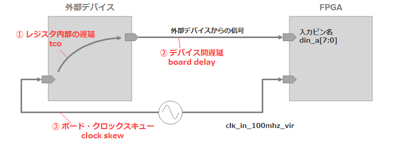
clk_in_100 mhz_vir is defined by the following formula.
create_clock - name clk_in_100 mhz_vir - period 10.000To define the delay for an externally applied signal on the 8-bit pin din_a [7:0],
Constrain the input setup time and input hold time.
There are three types of delays for data sent from external devices: 1, internal register delays, 2, board delays, and 3, board clock skews.
It is necessary to define an input delay that considers all of these.
For our example in this exercise, we will constrain the delay times defined in the table below.
|
minimum |
maximum |
|
| Register internal delay tco (ns) |
1 |
3 |
| board delay (ns) |
0.5 |
1 |
| Board Clock Skew clock skew (ns) |
-0.5 |
0.5 |
Table 1. Delay times
Use the table above to constrain the external data input for all input data pins.
Here is how to describe it
set_input_delay-clock {外部レジスタを駆動するクロック} - max 最大入力遅延[ get_ports {入力ピン名}] set_input_delay-clock {外部レジスタを駆動するクロック} - min 最小入力遅延[ get_ports {入力ピン名}]These two values, maximum input delay and minimum input delay, are obtained by the following formulas.
最大入力遅延= board delay ( max ) – clock skew ( min ) + tco ( max ) 最小入力遅延= board delay ( min ) – clock skew ( max ) + tco ( min )(The maximum input delay constrains the setup, and the minimum input delay constrains the hold time.)
In other words, in the example of this exercise, write the following two lines for din_a[0].
set_input_delay -clock {clk_in_100mhz_vir } -max 4.5 [get_ports {din_a[0]}] set_input_delay -clock {clk_in_100mhz_vir } -min 1 [get_ports {din_a[0]}]If this is described all from din_a[0] to din_a[7], it will be as follows.
set_input_delay -clock {clk_in_100mhz_vir } -max 4.5 [get_ports {din_a[0]}] set_input_delay -clock {clk_in_100mhz_vir } -min 1 [get_ports {din_a[0]}] set_input_delay -clock {clk_in_100mhz_vir } -max 4.5 [get_ports {din_a[1]}] set_input_delay -clock {clk_in_100mhz_vir } -min 1 [get_ports {din_a[1]}] set_input_delay -clock {clk_in_100mhz_vir } -max 4.5 [get_ports {din_a[2]}] set_input_delay -clock {clk_in_100mhz_vir } -min 1 [get_ports {din_a[2]}] set_input_delay -clock {clk_in_100mhz_vir } -max 4.5 [get_ports {din_a[3]}] set_input_delay -clock {clk_in_100mhz_vir } -min 1 [get_ports {din_a[3]}] set_input_delay -clock {clk_in_100mhz_vir } -max 4.5 [get_ports {din_a[4]}] set_input_delay -clock {clk_in_100mhz_vir } -min 1 [get_ports {din_a[4]}] set_input_delay -clock {clk_in_100mhz_vir } -max 4.5 [get_ports {din_a[5]}] set_input_delay -clock {clk_in_100mhz_vir } -min 1 [get_ports {din_a[5]}] set_input_delay -clock {clk_in_100mhz_vir } -max 4.5 [get_ports {din_a[6]}] set_input_delay -clock {clk_in_100mhz_vir } -min 1 [get_ports {din_a[6]}] set_input_delay -clock {clk_in_100mhz_vir } -max 4.5 [get_ports {din_a[7]}] set_input_delay -clock {clk_in_100mhz_vir } -min 1 [get_ports {din_a[7]}]Now the input pin constraint from the external signal is perfect! !
However, if the above were to constrain not only the din_a pin, but all other pins, it would not be a little troublesome and not a smart description.
(Because almost the same content is written for 16 lines ...)
When I was wondering if there was a way to describe it more neatly,
The senior who was in charge of the lecturer has a way to get by with two lines! He told me.
Here it is.
set_input_delay -clock {clk_in_100mhz_vir } -max 4.5 [get_ports {din_a*}]
set_input_delay -clock {clk_in_100mhz_vir } -min 1 [get_ports {din_a*}]
By putting an * (asterisk) after a , you can write the same statement whatever is written below din_a .
In other words, the previous 16 lines can be written in 2 lines.
This "*" is called a wild card, and you can write SDC files without much effort.
It seems that wildcards are often used in information processing (Linux, C language, etc.).
(I didn't know the wild card, so I was impressed when I learned about it during training lol)
This wildcard can also be used in SDC files, so why not use it!
Summary
・There are three elements of delay in the setting of the input pin, and all of them must be considered in the description.
・Using wildcards can reduce descriptions that span multiple lines. → Clear description + save time