- Semiconductor BusinessHOME
- Products and Services of Macnica,Inc.
-
technical information

-
Events and Seminars
- Handling Manufacturer
- Support
- Inquiry
- Click here to purchase products
- Semiconductor business e-mail magazine registration


 Narrow down by specifying conditions
現在2240件がヒットしています。check



Hello, this is Taro.
Last time I wrote about the frequency accuracy of the clock generator, but this time I will write about the matching of the crystal unit.
When using a crystal oscillator as a reference for a clock generator, the matching process, such as selecting capacitors according to the load capacitance of the clock generator, is important.
Difference between Crystal Unit and Crystal Oscillator
First, let me explain the difference between crystal units and crystal oscillators.
Since the crystal oscillator outputs the clock signal by inputting the power supply, it is possible to output the clock signal by itself.
Crystal oscillators are required for ICs that cannot configure a crystal oscillator circuit inside the IC, such as FPGAs, and for ICs that require the supply of clock signals.
Compared to crystal units, crystal oscillators have the disadvantage of being more expensive and having a larger package size.
A crystal oscillator does not have a crystal oscillation circuit, so it cannot output a clock signal by itself.
A crystal oscillator circuit is required to output the clock signal.
However, it is cheaper and has a smaller package size than crystal oscillators.
Therefore, crystal oscillators are often more advantageous when used as the source of oscillation for ICs such as clock generator ICs and CPUs that have a crystal oscillation circuit inside.
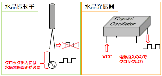
As described above, crystal units/crystal oscillators have advantages/disadvantages, so it is necessary to use them on a case-by-case basis.
Crystal oscillator circuit configuration
Let's get to the point. What is the configuration of the crystal oscillation circuit required for the crystal unit?
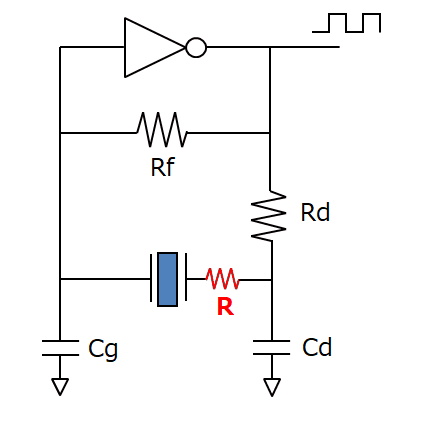
The CMOS gate-type crystal oscillator circuit and the role of each element are shown below.
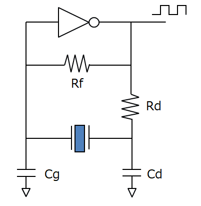
Rd : Limiting resistor - Prevents excessive current from flowing into the crystal unit.
Rf : Feedback resistor - Feeds back current from the inverter output side to sustain oscillation.
Cg : External Capacitor - Adjust negative resistance, excitation level and oscillation frequency.
Cd : External Capacitor - Adjusts negative resistance, excitation level and oscillation frequency.
Also, a crystal oscillator can be considered as an equivalent circuit as shown in the figure below.
A crystal can be treated as an equivalent circuit as shown in the figure below only at a specific frequency, so it can be said that the frequency stability is higher than that of an LC oscillator.
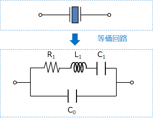
The data sheet of the crystal oscillator contains the values of C0 and frequency stability, and matching is performed based on these values.
Matching adjusts the oscillation frequency, oscillation margin, and excitation level.
Each adjustment method is described below.
Adjustment of oscillation frequency
The oscillation frequency is adjusted by matching the load capacitance CL with an external capacitor.
The relationship between frequency deviation and load capacity is as follows.
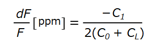
F: Oscillation frequency of crystal unit
dF: Difference between crystal oscillator oscillation frequency and actual frequency
The load capacitance CL is obtained by the following formula.
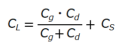
Cs: Oscillation frequency of crystal unit
By adjusting the values of Cg and Cd, the load capacitance of the crystal oscillator and the load capacitance of the crystal oscillation circuit are matched.
How does this load capacitance affect the frequency deviation?
The graph below shows the relationship between frequency stability and load capacity.

From this graph, we can see that frequency accuracy can vary greatly depending on the value of load capacitance CL.
Depending on the value of r, a 1 pF load capacitance error can cause a 29 ppm change in frequency deviation, so capacitance matching is important regardless of the frequency accuracy stated in the datasheet. I understand that.
Also, it can be said that the larger the load capacity, the smaller the frequency deviation and the higher the frequency accuracy.
However, along with the miniaturization of crystal oscillators, the load capacitance is becoming smaller.
Also, due to the balance between oscillation margin and excitation level described below, a large load capacitance does not necessarily supply a stable clock signal.
Adjustment of oscillation margin
Oscillation margin indicates the ability of the crystal oscillator circuit to oscillate the crystal unit.
The oscillation margin is determined by the equivalent resistance Re of the crystal oscillator circuit including the negative resistance RN and the crystal oscillator.
Here, negative resistance is a resistance with a negative resistance value that does not actually exist, which is generated when configuring a crystal oscillation circuit.
To measure negative resistance, insert a variable resistor R into the crystal oscillator circuit as shown below.
As the resistance value of the variable resistor is increased, the resistance value when oscillation stops is the resistance value of the negative resistance.
The figure below shows the relationship between the negative resistance R, the inserted resistance RN, and the equivalent resistance Re of the crystal oscillation circuit.
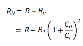
RN: Negative resistance
Re: resistance when load is connected
R: insertion resistance
The oscillation margin is expressed as RN / Re. If the oscillation margin value is 5 or more, the clock will be output stably.
If the oscillation margin is too small, the crystal may not oscillate and the clock may not be output.
To improve the oscillation margin, it is necessary to increase the value of RN and decrease Re.
There are two ways to increase the value of RN.
The first is to reduce the value of the external capacitor.
However, if the external capacitor is made smaller, there is a risk that it will not be able to match the load capacitance of the crystal unit.
When reducing the value of the external capacitor, it is necessary to consider the balance with frequency accuracy.
The second is to reduce the value of the limiting resistor.
Lowering the value of the limiting resistance increases the current that flows into the crystal oscillator, so it is necessary to consider the balance with the excitation level.
Also, in order to reduce Re, the crystal oscillator itself needs to be changed, so it is necessary to consult with the crystal oscillator vendor.
Adjustment of drive level (Drive Level: DL)
Finally, let's talk about drive levels.
Drive level represents the power applied to the crystal.
The drive level is specified in the crystal datasheet and is in watts ( W ).
The drive level DL is expressed by the following equation.
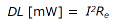
I: Current flowing through the crystal oscillator
If the excitation level becomes higher than the value specified in the datasheet, excessive current will flow through the crystal unit, which may lead to damage to the crystal.
Care should be taken not to apply more power to the crystal than the maximum drive level.
Is it possible to configure a crystal oscillator circuit with an FPGA?
Unfortunately, it is not possible to configure the crystal oscillator circuit inside the FPGA and attach the crystal oscillator externally.
This is because the inverter that the FPGA has is a logic inverter, which is not suitable for driving the output of a crystal oscillator as an amplifier circuit.
Even if you could build a crystal oscillator circuit in the FPGA and obtain a clock output, the clock would be less stable and less reliable.
Examples of unreliable clock failures include stopping oscillation when the temperature changes and oscillating when the board is touched.
A crystal oscillator circuit must operate correctly as an analog amplifier, and the characteristics of a crystal oscillator circuit are greatly affected by active elements such as ICs.
Summary
As mentioned above, various factors are intricately related to the design of the crystal oscillator circuit.
Using multiple crystal oscillators requires matching for each, which increases the number of man-hours.
Another option is to use a crystal oscillator, but it will inevitably cost more than a crystal unit.
We also have other clock buffers, so please feel free to contact us.