- Semiconductor BusinessHOME
- Products and Services of Macnica,Inc.
-
technical information

-
Events and Seminars
- Handling Manufacturer
- Support
- Inquiry
- Click here to purchase products
- Semiconductor business e-mail magazine registration


 Narrow down by specifying conditions
現在2237件がヒットしています。check


Hello, I'm Mass Man.
This is the fourth installment of the “Timing Analysis Series”.
The most difficult part of the new employee training was the lecture on timing analysis. In this column, I would like to summarize the lecture materials and notes on timing analysis and introduce the points where I stumbled.
The analysis results of the TimeQuest Timing Analyzer are expressed as "slack values". Let me introduce you to what this means!
Timing error if slack value is negative
Figure 1 shows the timing analysis results. The TimeQuest Timing Analyzer uses positive or negative slack values to determine whether timing constraints are met.

Figure 1. Part of the Timing Analysis Report
In Masuo's head, it was "timing error when slack value? is negative???". It was very difficult to understand the slack value. By understanding the following four parameters, I was able to understand the slack value.
・Data arrival time
・Clock Arrival
・Setup data required time (Setup Data Required)
・Hold data required time (Hold Data Required)
About the four parameters related to the slack value
In order to understand the slack value, we have kept four parameters.
Data Arrival
Time for data to arrive at the D input of the receive register.
From Fig. 2, (Equation 1) can be derived.

Figure 2. Schematic diagram of data arrival time
Clock Arrival
The arrival time of the clock at the clock input of the receiving register.
(Formula 2) can be derived from Fig. 3.

Figure 3. Schematic diagram of clock arrival time
Setup Data Required
The signal must arrive within this time for the receiving register to receive the data correctly.
(Formula 3) can be derived from Fig. 4.
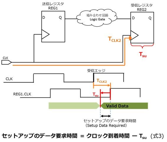
Figure 4. Schematic diagram of setup data request time
Hold Data Required Time
The signal must arrive after this time for the receiving register to receive the data correctly. Anything faster than this interferes with the data from the previous cycle.
(Formula 4) can be derived from Fig. 5.
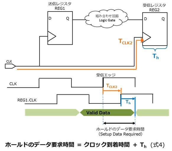
Figure 5. Schematic diagram of setup data request time
Slack value definition formula
I was able to understand the slack value from the definition formula of the operating frequency (Fmax) and the above four parameters. For the definition of the operating frequency (Fmax), see "Timing Analysis Series 1 Concept of Timing Analysis".

◆ Setup Slack
Setup slack is the timing margin within which setup data requirements are met. It guarantees that the data will arrive within that time to fill the latch.
setup slack = setup data request time - data arrival time
Here, substitute (formula 1) (formula 4)
= (clock arrival time - Tsu) - (transmission edge + TCLK1 + μTco + TdataDelay)
Here, substitute (Equation 2)
= (receive edge + TCLK2 - Tsu) - (transmit edge + TCLK1 + μTco + TdataDelay)
= (receive edge - transmit edge) + TdataDelay + (TCLK2 - TCLK1) - Tsu - μTco
Here, substitute (Equation 5)
= 1 clock cycle - 1/Fmax
*1 clock cycle is the desired operating frequency. 1/Fmax is the calculated operating frequency.
◆Hold Slack
Hold slack is the timing margin within which the hold data request time is met. Ensures latched data is not interfered with by data from another rising edge. It also prevents data penetration.
hold slack = data arrival time - hold data request time
= 1 clock cycle - 1/Fmax
*1 clock cycle is the desired operating frequency. 1/Fmax is the calculated operating frequency.
therefore,

From (Equation 6), the slack value is the difference between the "desired operating frequency" and the "operating frequency calculated for the feasibility of the actual user design".
In other words, the slack value is the gap between the “ideal” and “real” operating frequencies.
Every day, Masuo also struggles to face the gap between ideal and reality. We are working hard every day to get even one step closer to our ideal! !
| Summary |
|---|
|