- 半導体事業HOME
- マクニカの製品・サービス
-
技術情報

-
イベント・セミナー
- 取扱メーカー
- サポート
- お問い合わせ
- 製品購入はこちら
- 半導体事業のメルマガ登録
![]()
![]() 条件を指定して絞り込む
条件を指定して絞り込む
現在2189件がヒットしています。check

いざ、モーターアプリケーションの制御を開発するとなるとマイコンで開発しようと考えるエンジニアは多いのではないでしょうか?
しかし、マイコンで設計した場合、下記のような課題に直面します。
- 長期的に製品供給するアプリケーションなのにマイコンが生産中止
- モーターを複数制御したいがマイコンの PWM などペリフェラルが足りない
- モーター制御と通信処理を同時に動作したらパフォーマンスが足りなかった
など実際に開発の現場ではよく話を聞きます。
しかし、FPGA を採用することでこれらの問題を解決することが可能です。
FPGA を採用するメリット、デメリットも含めて解説します。
FPGA でモーター制御をおこなう3つの理由
[理由1] 処理速度がマイコンと比較して圧倒的に速い
一般的なマイコンは性能があがったとはいえ、μsec での処理速度です。
FPGA ではローエンド向け FPGA でも nsec での処理が可能であり処理速度はマイコンと比較して圧倒的です。
FPGA はハードウェアで処理するため、モータ制御で必要な PWM などの処理が得意です。
マイコンのソフトウェアでの処理速度と比較すると数倍〜100倍以上の差がでるからです。
[理由2] 複数のモーターを同時に処理できる
産業機器、FA ロボットなど、1つのアプリケーションで10個、20個のモーターを制御しなければならい状況はどんどん増えています。
これらの処理を1個のマイコンで処理することはできるのでしょうか?10個のモーターを同時に制御するなど不可能です。
そもそも、制御に必要な PWM が数十個搭載したマイコンは存在しません。
しかし、FPGA であれば数十個の PWM を搭載することは容易にできます。また、FPGA 内部に CPU を搭載することもできるため、1個の FPGA で数十個のモーターを制御することも可能です。
[理由3] 長期供給が可能
産業機器向けアプリケーションを供給しているメーカーの最大の悩みは生産中止です。
マイコンが生産中止になった場合、ほとんどの場合において、御社の製品の製造中止を意味します。
よほど、しっかりとした後継マイコンを供給してもらえない限り継続しての生産はできないでしょう。
Altera® は ほとんどの FPGA を長期供給しています。製造開始から20年以上たっても市場に供給し続けている製品もあります。もし、万が一 FPGA が生産中止になったとしても、後継の FPGA に設計ソースを移植することが簡単にできます。
つまり、後継の FPGA で同じ機能が継続して利用できます。
そうはいっても、1個のモーター制御で十分という場合はマイコンで事足りますし FPGA を利用することのデメリットもあります。
FPGA を使うデメリットもあります
[デメリット1] 動作には複数電源が必要
一般的な FPGA ではコア電源と I/0 電源が分かれています。
例えば FPGA はコア電源が 1.2V に加えて、インターフェース毎に I/O 電源が必要です。
メモリーや差動信号、LVCMOS などインターフェース毎に複数の電源が必要になります。
FPGA の電源周辺がマイコンと比較して設計が面倒というデメリットがあります。
しかし、Altera® の最新デバイス MAX® 10 シリーズは 3.3V 単一で動作する FPGA も販売されており、デメリットも解消されつつあります。
[デメリット2] コンフィグレーション ROM が必要
一般的な FPGA は SRAM ベースで設計されているため、電源を落とすと、FPGA 内部の回路データは消えてしまいます。そのため、FPGA を立ち上げるたびに外部の ROM からコンフィグレーションが必要です。
このことが FPGA が2チップ構成が必要になり、外部 ROM がコストアップの原因にもなっています。
しかし、Altera® の最新デバイス MAX® 10 シリーズは FPGA 内部に Flash メモリーを搭載しておりワンチップでの FPGA 動作を実現しています。このデメリットは解消されています。
[デメリット3] マイコンと比較して単価が高い
ひと昔前の FPGA は1個あたり、数千円〜数万円というのが相場でした。そのため、マイコンと比較すると数倍の値段がするということもよくありました。
しかし、現在はプロセスの微細化が進み、低価格帯の FPGA も普及がすすんでいます。購入数量にもよりますが、モータ制御に使える FPGA が数ドルで買えるような状況になってきています。
以上のようにマイコンと比較して FPGA でモータ制御を実現するにはデメリットもあるものの、最新の Altera® FPGA ではそのデメリットも解消されています。
複数のモーターを制御が必要な高付加価値のアプリケーションの開発には FPGA を採用するケースが増えています。
とはいえ、モータ制御を FPGA で ゼロから作って評価するのはかなり大変です
これはマイコンにも言えることですが、何も状態からモータ制御の回路を FPGA でいきなり開発するのはかなり大変です。
マイコンであれば、ペリフェラルに合わせてソフトを開発することもできますが、FPGA の場合はそのペリフェラルから開発するようなものです。
ですから、開発キットやリファレンスデザインなどを使って FPGA を開発するのがもっともベストな方法です。
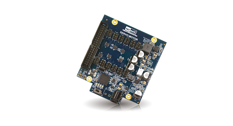
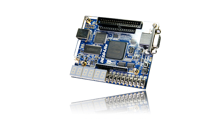
すぐに使えるサーボモーター開発キット「DE10 Lite」と「Servo Motor Kit」
「Servo Motor Kit」は Terasic 社製の FPGA 開発キットです。Altera® FPGA の最新デバイス MAX® 10 が搭載された「DE10 Lite」とつなぎ合わせることですぐにサーボモーター制御の評価ができます。
「Servo Motor Kit」には最大24個のサーボモーターを接続して同時に制御することができます。
また、サーボモーター制御に必要なリファレエレンスデザインも付属しているため動作確認後、このリファレンスデザインを元にすぐに開発がおこなえます。
開発キットには回路図面、部品リストも付属しているのでこの図面とリストを参考に基板設計も容易におこなうことができます。
開発ツールは無償で使えます
この開発キット「DE10 Lite」には搭載されている、FPGA は Altera® の無償開発ソフト「Quartus Prime ライト・エディション」で開発がおこなえます。
また、デバッグやプログラムの書き込みは開発キットに専用回路が実装されているため、PC と開発キットを付属の USB ケーブルでつなぐだけで開発がおこなえます。
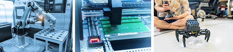
アプリケーション例
- FAロボット
- 工作機器
- アクチュエーター
開発キット「DE10 Lite」「Servo Motor Kit」の詳細
FPGA 開発キット「DE10 Lite」
| メーカー名 | terasic |
| 型 名 | P0466 / DE10 Lite |
| 搭載 FPGA |
|
| Memory Device | 64MB SDRAM, x16 bits data bus |
| Expansion Connectors |
|
| Display | 4-bit Resistor VGA |
| Switches/Buttons/ LEDs/7-Segment Display |
|
| 付属品一覧 |
|
ドーターカード「Servo Motor Kit」
| メーカー名 | terasic |
| 型 名 | P0288 / Servo Motor Kit |
| 機能詳細 |
|
| 付属サーボモータ |
|
| 付属品一覧 |
|