- Semiconductor BusinessHOME
- Products and Services of Macnica,Inc.
-
technical information

-
Events and Seminars
- Handling Manufacturer
- Support
- Inquiry
- Click here to purchase products
- Semiconductor business e-mail magazine registration


 Narrow down by specifying conditions
現在2247件がヒットしています。check


Before compiling in FPGA development, it is important to check whether the created logic circuit (design) operates as expected.
It's important.
Today, hardware language (HDL) is the mainstream of design, and logic simulation is also done in language.
Input pattern information is indispensable for simulation, and the input pattern is also described by the designer in HDL, which is called a "testbench".
Here is a very basic description of a testbench.
Module format
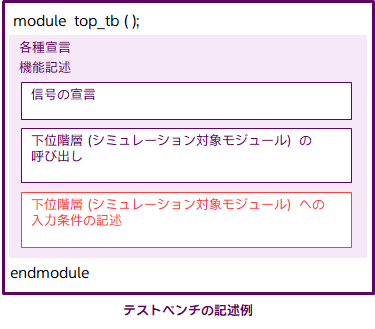
For Verilog-HDL, when creating a testbench, you start with module <module name> just like when creating a design. However, since testbench generally does not have input/output ports, there is no need to write the port list after the module name. Also, no input/output port declarations are required. Therefore, the input conditions of signals to be input to the design to be verified are described in HDL in various declarations and function descriptions.
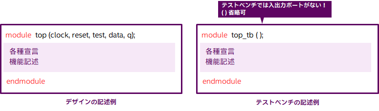
Module format (details) & signal declarations
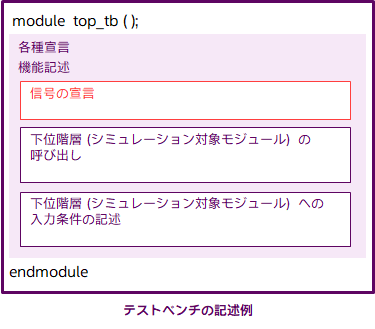
"Various declarations and function descriptions" can be divided into "signal declarations", "calls to the lower layer (simulation target module)", and "description of input conditions to the lower layer (simulation target module)". increase. As mentioned earlier, there is no input/output port in the testbench, so there is no need to declare port attributes using input, output, and inout. In the test bench, declare the data type of the signal used as the test input as a register (reg declaration), and conversely declare the data type of the signal that does not give a value in the test bench connected to the output port to be verified as a wire declaration (wire declaration)..
example)
reg clock, reset, test;
reg [7:0] data;
wire [7:0] q;
Calling the lower layer (simulated module)
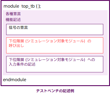
The section "Calling the lower level (simulated module)" is exactly the same as the description of calling the lower level generally used in the design.
The following is an example where the instance name of the simulation target module is “u1”.
example)
top u1 (
.clock (clock),
.reset (reset),
.test (test),
.data (data),
.q (q)
);
Description of input conditions to the lower layer (simulation target module)
Next, I will explain "Description of input conditions to the lower layer (simulation target module)". Here we mainly
- Describe a signal whose level is always fixed
- Describe a signal whose value increments at regular intervals
- Description of signals that repeat '1' (H level) and '0' (L level) irregularly
- Description of a signal that periodically repeats '1' (H level) and '0' (L level)
This section explains. Once you've mastered these, you'll be able to write your own testbenches.
Note that there are other description methods other than those introduced here, so please study and master them later.
1. Description of a signal whose level is always fixed
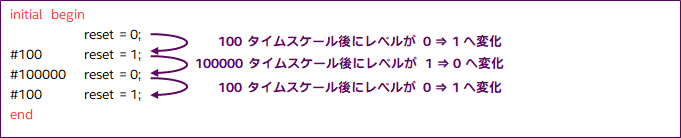
Write the initial statement at the beginning of the simulation. The expression you have written is executed only once. For signals whose level does not change during the simulation run, the initial statement should be followed by the signal name and level.

2. Description of a signal whose value increments at regular intervals
First, write the initial value after initialbegin. Then use the always statement to write an expression that increments at regular intervals.

3. Description of signals that repeat '1' (H level) and '0' (L level) irregularly
For a signal whose level changes irregularly, use begin to end in one initial statement and describe multiple expressions between them.
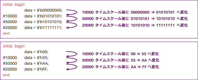
A signal that consists of multiple bits such as a bus is described as follows. For an 8-bit signal, write the level of each bit after 8'b. b means binary number. Hexadecimal display is also possible using h.
4. Description of signals that periodically repeat '1' (H level) and '0' (L level)
When describing a signal that periodically repeats '1' (H level) and '0' (L level) like a clock, it is not necessary to describe it forever using the method described earlier. To do. Two description methods are introduced here. Both have the same input conditions.
- Method 1

- Method 2

sample design
You can download the exercise data for reference from the following page. This sample also uses the description of the testbench, so please refer to it.
Coffee break: `timescale

Have you ever seen ` timescale mentioned at the beginning of a testbench? This is a description to specify the unit of simulation time.
Describe with units (fs, ps, ns, us, ms, s). The `timescale description is usually written only in the testbench.
`timescale <real time per timescale>/<rounding precision>
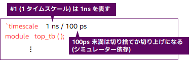
As for the position of the simulation time in the expression, either of the following is fine.

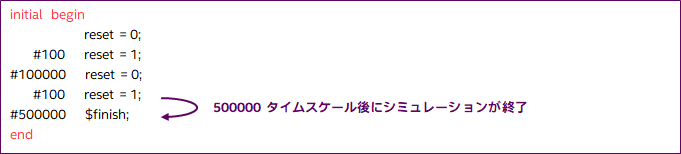
Coffee break: $finish

You will see the statement $finish in the expression in the testbench. This means that the simulation will end when it runs to this line. Without this $finish the simulation will not finish. If you run a simulation with a specified time, it will end even if there is no $finish, but if you run a simulation without specifying a time, find this $finish and end it when it reaches it. Let's put this $finish in one place!