- Semiconductor BusinessHOME
- Products and Services of Macnica,Inc.
-
technical information

-
Events and Seminars
- Handling Manufacturer
- Support
- Inquiry
- Click here to purchase products
- Semiconductor business e-mail magazine registration
![]()
![]() Narrow down by specifying conditions
Narrow down by specifying conditions
現在2149件がヒットしています。check
![[Comprehensive Explanation] MIPI is not difficult! Newbies learn the MIPI standard from scratch ~ Basics Part 4 CSI-2 ~](/business/semiconductor/articles/0004ee9b117a10887cf6e5889a1888cc_25.png)
Hello! I'm Hiromin from Lattice team rookie FAE!
This blog is my study process about MIPI standards.
What is MIPI? What are the differences between the DSI/CSI-2 standards? How to design with Lattice FPGA?
From the basics to applications, I would like to tell you everything I have learned!
Now, this time, I would like to learn about MIPI CSI-2 according to the table of contents below.
You can also go directly to the part you want to learn by the links below, please check it out!
[What you can learn from this article]
Learn about CSI-2!
・ Let's review from the video frame diagram!
・ Packet configuration for MIPI transmission
• Packet Details - What is the packet format?
You can read the previous article, MIPI DSI Part 2, from the link below!
Also, if you would like to review what we have covered so far, you can view it at the blog summary link below!
Let's review from the video frame diagram!
Second article explained in video frame diagram Let's review how MIPI packets are arranged in a video frame.
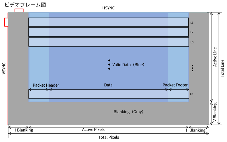
A video frame diagram can be divided into a gray part and a blue part.
The gray area is composed of blanking and is the area where the image is not displayed.
On the other hand, the blue part consists of Packet Header/Footer and Data, and the data part where the image is actually displayed is Valid Data.
It is sent in order of Blanking → Packet Header → Valid Data → Packet Footer → Blanking.
This will be 1 line. By sending multiple Lines of this Line, one image is created.
The size of a single image is called resolution or angle of view.
This refers to the size of the area where the video is displayed (horizontal pixels x vertical pixels), and is expressed as SD, HD, full HD, and 4K.
If you switch this one image like a flipbook, it will become a video.
Also, there is a rule for the speed of flipping.
The unit that indicates how many images constitute one second of video is called Frame Rate (fps).
The video is constructed as described above.
Since MIPI is a communication standard, there is of course the concept of Data Rate.
The total data rate can be calculated by horizontal pixel x vertical pixel x Frame Rate (fps) x Data Format (bit).
What did you think? I had a lot of vague recollections, so it was a good review!
Next, I would like to take a look at the packet structure of MIPI!
Packet structure for MIPI transmission
In order to understand CSI-2 from now on, I would like to divide it into the following three segments as in the DSI edition.
Let's start with the packet structure.

As I mentioned a little in the DSI edition, the packet configuration is the same for DSI/CSI-2.
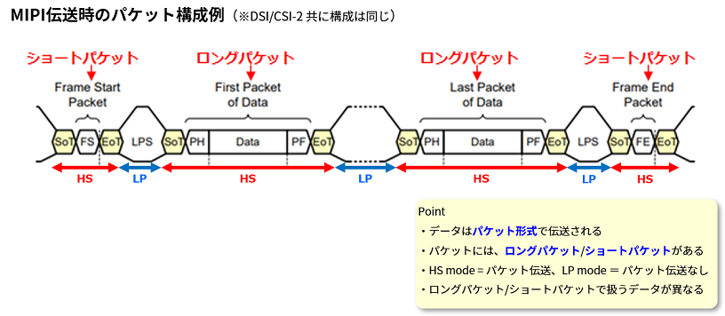
MIPI data is transmitted in packet format, divided into short packets and long packets. Each handles different data.
In addition, packet transmission is performed in HS mode, and packet transmission is not performed in LP mode.
The term Frame Start/End came up. Do you remember? ? Let's review the previous video frame diagram.

A more detailed summary of the previous video frame diagram. Video = image flipbook, so the first step is to create an image.
In order to make an image, the image is output for each line. If you output multiple lines of it, it becomes an image.
Frame Start/End determines the vertical range of the image, and Line Start/End determines the horizontal range.
Therefore, information related to video timing such as Frame Start/End and Line Start/End is stored in short packets, and actual effective image data is stored in long packets.
The video we actually see is what is being transmitted by long packets, and the timing of outputting long packets is controlled by short packets.
From the next chapter, I would like to see the details of the packet!
Packet Details - What is the packet format?

Now let's learn about CSI-2 packets. Compared to DSI, there are some differences, so I would like to mainly learn the differences.
The image of CSI-2 short packet and long packet is as follows.

A CSI-2 long packet consists of Data ID, Wrod Count (WC), Data, Check Sum, and ECC. CSI-2 transmissions are dominated by long packets.
It is the part of "Sync Code "0 x B8"" shown in red. What is this?
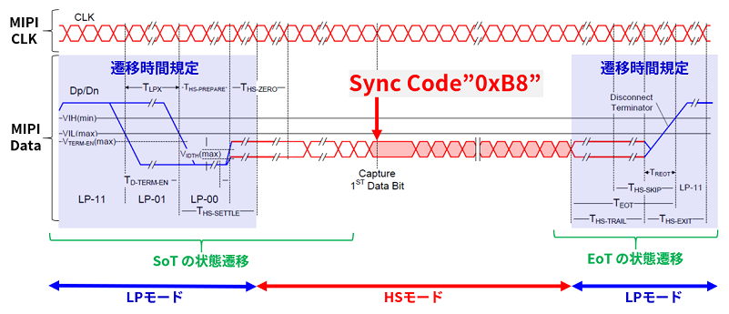
Sync Code is used to detect the start position of HS mode. Immediately after the transition from LP to HS, this Sync Code is checked to detect where the head of HS mode is.
This seems to be a common DSI/CSI-2 transmission. It didn't come up when I looked up DSI, so it's a new discovery!
Let's go back to the packet details from earlier.
A short packet consists of Data ID, 16Bit Short Packet Data Field, and ECC.
Packet Details - Data ID
First is the Data ID. This Data ID is used in common for CSI-2 short packets/long packets.
The data stored in the Data Type is different for each short packet/long packet. Even if you compare it with the DSI DataID, I think the contents of the data are different.

The main configuration of Data ID consists of Virtual Channel (VC) 2bit and Data Type 6bit, a total of 8bit.
VC is used for display labeling purposes. For example, if there are two displays, label them as VC1 and VC2 respectively with the VC in the Data ID.
Data Type is literally used to identify the Data Type of the effective image data (Packet Data) part. The type in the bottom right table determines what data will be sent.
Now you understand the main structure of Data ID!
I explained that CSI-2 long packets and short packets handle different data, but what are the differences?
Data ID Difference in short packet/long packet

As a difference, there seems to be a difference in the contents of Data Type.
Video timing information such as Frame Start/End and Line Start/End is stored in Data Type in CSI-2 short packet. This seems to be called Synchronization Short Packet Data Type.
Also, the Data Type in the CSI-2 long packet contains the Data Format of the effective image Data part.
Comparing this part with DSI short packet / long packet, I think that the contents of the data are slightly different.
Now that we understand Data ID, let's take a look at the details of WC, 16Bit Short Packet Data Field, and ECC/Check Sum!
Packet Details - WC
Next, I would like to look at WC, 16Bit Short Packet Data Field, Error Correction Code (ECC), and Check Sum in that order.
WC consists of 2 bytes, and plays the role of notifying how many bytes of data are sent in Packet Data.
Since this WC is variable by Packet Data, it is variable by resolution and Data Format.

Packet Details - 16Bit Short Packet Data Field
Next is the 16Bit Short Packet Data Field. 16Bit Short Packet Data Field consists of 2 bytes.
It seems that the data called Frame number / Line number is stored in this 2Byte.
Frame number is stored in this 16Bit Short Packet Data Field when Frame start code (0x00) and Frame end code (0x01) are stored in the previous Data ID.
Line number is stored when Line start code (0x02) and Line end code (0x03) are stored in the previous Data ID.
This part is different from DSI! informative.
Finally, let's look at ECC/Check Sum.

Packet Details - ECC/Check Sum
ECC and Check Sum mainly perform error detection and correction to check whether the information sent is correct.
Error detection and error correction are used to detect and correct erroneous data when erroneous data is sent and received due to the effects of noise and other factors.

ECC is capable of detecting and confirming whether or not garbled bits have occurred for a total of 24 bits of Data ID and WC.
1bit error correction and 2bit error detection are possible.
Also, Check Sum is an error detection used in Footer of long packet,
It is possible to detect and confirm whether bit garbling occurs in the effective image data part.
Click here to download the MIPI CSI-2 Comprehensive Dictionary!
From here, the content such as the positional relationship of short packets / long packets and the Lane Distribution Function becomes difficult as in the DSI edition, as shown in the image below, so it is difficult for Hiromin to understand and share with everyone. is.
Therefore, with the full cooperation of MIPI Maestro G-senpai, who covers all of the MIPI standards, we have created the "All in One Book!MIPI D-PHYEncyclopediaCSI-2"!
We plan to describe all the contents of MIPI CSI-2, including the contents of D-PHY explained in the second article.
Please feel free to download it and use it as a reference for your development with MIPI D-PHY and DSI.
▼▽▼▽▼▽▼▽▼▽▼▽▼▽▼▽▼▽▼▽▼▽
Learn everything in this one book! MIPI D-PHY Encyclopedia ~CSI-2 Edition~

From next time onwards, we will be compiling articles on the advantages and disadvantages of implementing the MIPI standard with FPGAs, articles on FPGA MIPI I/F case studies, and articles on points to consider when considering specifications/frequently asked questions.
See you next time!
Market needs and challenges for MIPI interfaces: What chips and ICs can be used to achieve this?
See you there! Bye~

New Engineer's Struggle ~MIPI Standard Version~
The MIPI standard is a communication standard often used in recent years for display interfaces and image sensor output interfaces.
I know the name of the standard, but what is the communication band? What protocol are you using?
Among MIPI, this article focuses on DSI/CSI for newcomers to study from scratch.
We are creating articles about the MIPI standard with the motto of making it easier to understand and more fun than other articles.
Would you like to study with a newcomer?