- 半導体事業HOME
- マクニカの製品・サービス
-
技術情報

-
イベント・セミナー
- 取扱メーカー
- サポート
- お問い合わせ
- 製品購入はこちら
- 半導体事業のメルマガ登録
![]()
![]() 条件を指定して絞り込む
条件を指定して絞り込む
現在2003件がヒットしています。check


こんにちは。
マクニカでインテル® FPGA 製品の技術サポートをしている インテル・F・ハナコ です。
以前ご紹介した
FPGA システム・デバッグ・ツール "System Console" を使ってみよう
では、System Console 上で実行する System Console コマンドをその都度 Tcl Console ペインに入力しましたが、Toolkit API サービスを活用すると、デザインのデバッグデータを視覚化して操作するカスタムツールが作成できます。Toolkit API は、デバッグロジックとの通信にユーザーの入力が活用できるボタンやテキストフィールドといった形式の視覚的なウィジェットを提供します。
今回は、System Console における Toolkit API 使用方法をご紹介します。
対象環境
|
Quartus® Prime |
Standard Edition / Lite Edition |
|
対象デバイス |
Quartus Prime の上記エディションがサポートする全デバイス |
|
通信ケーブル |
・インテル FPGA ダウンロード・ケーブル II (旧称 USB-Blaster II) ・On-Board インテル FPGA ダウンロード・ケーブルII ・インテル FPGA ダウンロード・ケーブル (旧称 USB-Blaster) ・On-Board インテル FPGA ダウンロード・ケーブル |
| デザイン必須条件 |
プロジェクト・デザインに、以下のいずれかのペリフェラルが組み込まれていること。 ・ JTAG to Avalon Master Bridge (JTAG Master) ・ Nios II Processor (JTAG Debug モジュール付き) ・ USB Debug Master ・ Avalon-ST (Streaming) JTAG Interface ・ JTAG UART ・ Ethernet コンポーネント |
Note:
Pro Edition でも Toolkit API を使用できますが、Pro Edition 19.1 以降は新しいフレームワークをご利用ください。
サンプルデザイン
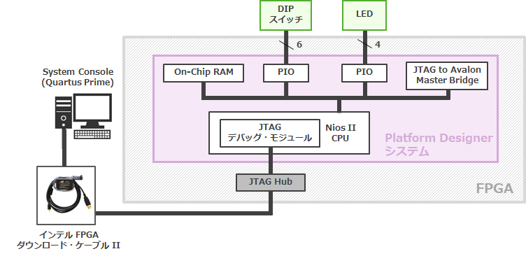
ここで使用するサンプルデザインの構成は、以下のとおりです。
今回は System Console で Toolkit API を使用して、DIP スイッチの PIO、LED の PIO、オンチップ RAM へのアクセスを、ウィジェットにより視覚化して操作します。
ウィジェットの種類
作成できるウィジェットは複数あります。
例えば、ボタン、チェックボックス、コンボボックス、テキストボックス、LED、棒グラフ、円グラフ などが構成できます。
これらのウィジェットは、組み合わせて構成することにより、操作性が向上します。
ウィジェットのタイプやプロパティーについては、下記ドキュメントをご覧ください。
(「Intel Quartus Prime Standard Edition User Guide: Debug Tools」> Analyzing and Debugging Designs with System Console より)
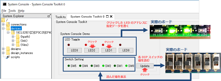
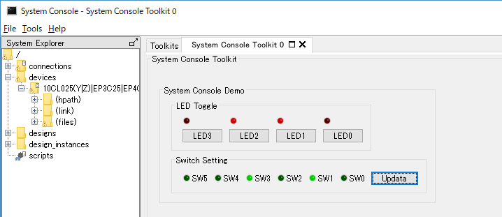
例えば、サンプルデザインに対して Toolkit API を使用すると、このような GUI で制御できます。
[サンプル A]
・ ボタンウィジェットをクリックして、LED の点灯/消灯を制御する
・ DIP スイッチの ON/OFF 状態を読み出し、LED ウィジェットに表示する
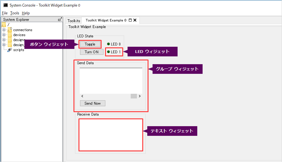
また、別のウェジットにより、以下のような操作性の異なる GUI を構成できます。
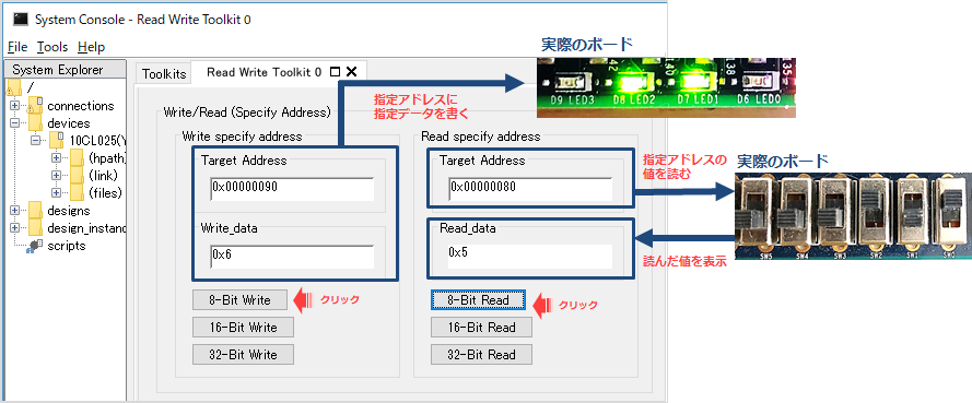
[サンプル B]
・ LED PIO のアドレスと書き込む値をテキストウィジェットに指定し、LED の点灯/消灯を制御する
・ DIP スイッチ PIO アドレスの値を読み出し、テキストウィジェットに表示する
作業フロー
Toolkit API を使用して作成する Toolkit には、以下のファイルが必要です。
・Toolkit GUI を実装するスクリプトファイル (.tcl)
・Toolkit 記述ファイル (.toolkit)
Toolkit API GUI を起動するまでの作業フローは以下のとおりです。
ここでは、[サンプル A] を題材にして説明します。
(このサンプルにおける LED 用 PIO のアドレスは、0x90 としています。)
1. Toolkit API スクリプトファイル (.tcl) を作成
Toolkit API サービスを使用するために、GUI を構築するためのスクリプトを作成します。
ここでは、Toolkit API スクリプトの一例を紹介します。
● Toolkit を可視化
System Console 上で Toolkit を可視化するため、toolkit_set_property コマンドと visible プロパティーを使用します。
以下は、例です。
toolkit_set_property self visible truevisible プロパティ―を True に設定すると、GUI でウィジェットが表示されます。
プロパティーがツールキット全体に提供されている場合は、self を使用します。
それ以外の場合は、all を使用してルート・ツールキットを参照します。
なお ここで使用している toolkit_set_property コマンドの構文は以下のとおりです。
toolkit_set_property <id> <propertyName> <value>
引数
<id> 編集されているウィジェットの一意のID
<propertyName> 設定されているウィジェット・プロパティーの名称
<value> ウィジェット・プロパティーの新しい値
● ウィジェットの追加と設定
ウィジェットを追加するため、toolkit_add コマンドを使用します。
toolkit_add コマンドの構文は以下のとおりです。
toolkit_add <id> <type> <groupid>
引数
<id> 追加されているウィジェットの一意のID
<type> 追加されているウィジェットのタイプ
<groupid> 新しいウィジェットを含む親グループのID
また、作成したウィジェットの詳細は、toolkit_set_property コマンドにより設定します。
例えば、テキストボックス用ウィジェットであれば、初期表示の設定や、テキストボックスの幅の設定ができ、
グループ用ウィジェットであれば、グループウィジェット内で 1 行内に配置するウィジェットの数を設定できます。
(toolkit_set_property コマンドの構文は、”Toolkit を可視化” のセクションを参照してください。)
以下は、LED ウィジェットで SW0 (下図右下の赤枠 参照) を構築する際の例です。
toolkit_add  SW0 led leds          # LED ウィジェット SW0 を追加
toolkit_set_property  SW0 text "SW0"    # SW0 はテキストで SW0 と表示
toolkit_set_property  SW0 color green_off   # SW0 は 緑色(消灯)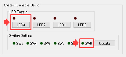
LED3 (上図左上の赤枠 参照) のように、LED とボタンを構築する際は、以下のように記述します。
toolkit_add  LED3_led led buttons          # LED ウィジェット LED3_led を追加
toolkit_set_property  LED3_led text " "        # LED3_led はテキストで表示なし
toolkit_set_property  LED3_led color red_off     # LED3_led は赤(消灯)

toolkit_add  LED3 button buttons          # ボタンウィジェット LED3 を追加
toolkit_set_property  LED3 text "LED3"        # LED3 はテキストで LED3 と表示
toolkit_set_property  LED3 onClick {toggle_led  3}   # LED3 はクリックするたびに {} を実行
● イベントを追加
一部のウィジェットは、コールバックと呼ばれるユーザー指定の動作を実行します。
例えば、テキストフィールドウィジェットの onChange プロパティーは、テキストの内容が変更すると呼び出されます。
ボタンウィジェットの onClick は、ボタンをクリックすると呼び出されます。
コールバックは、テキストフィールドの内容や他のウィジェットの状態に基づいてウィジェットを更新したり、サービスと通信したりします。
コールバックをトリガとしてイベント登録するには、プロシージャ (proc コマンド) を定義します。
proc コマンドの構文は以下の通りです。
proc <name> {args} {body}
引数
<name> プロシージャ名
{args} 変数リスト
{body} Tcl スクリプト
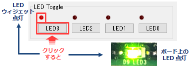
例えば、LED3 と明記されたボタンウジェットをクリックして、ボード上の LED3 を点灯させ (アドレス 0x90 に値を書き込む)、
同時に LED ウィジェットを点灯させるには、以下のように記述します。
# This Procedure toggles the LED when you push the button on the toolkit
proc toggle_led {led } {
	global master_path
	set led_read [master_read_8 $master_path 0x90 1]

	# (LED0~LED2 用のコード省略)

	if {$led == 3 }  {
	  set led_set [expr 8 ^ $led_read] }

  	master_write_8 $master_path 0x90 $led_set

	set led_read [master_read_8 $master_path 0x90 1]

	# (LED0~LED2 用のコード省略)

	if { [expr {$led_read & 8}] == 8 } {
   	   toolkit_set_property  LED3_led color red
		}

	if { [expr {$led_read & 8}] == 0 } {
   	   toolkit_set_property  LED3_led color red_off
		}
}2. Toolkit 記述ファイル (.toolkit) を作成
作成した Toolkit API スクリプトファイルを適用させる Toolkit 記述ファイルを作成します。
Toolkit 記述ファイル (.toolkit) は、Toolkit の登録データを提供する XML ファイルです。
以下はサンプルです。
<?xml version="1.0" encoding="UTF-8"?>
<toolkit name="system console toolkit" displayName="System Console Toolkit" addMenuItem="false">
	<file> toolkit_script.tcl </file>
</toolkit>
.toolkit ファイルに必要な属性や子エレメントについては、下記ドキュメントをご覧ください。
Creating a Toolkit Description File
(「Intel Quartus Prime Standard Edition User Guide: Debug Tools」> Analyzing and Debugging Designs with System Console より)
3. Toolkit を登録
Toolkit を使用するため、以下の手順に従い System Console 上で toolkit_register コマンドを実行します。
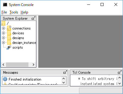
① System Console を起動します。
② (System Console 起動前に Programmer で .sof をダウンロード済みの場合は、④ へ進みます。)
File メニュー > Load Design ボタンをクリックし、ダウンロードする .sof を選択します。
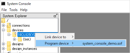
③ System Explorer ペインの devices フォルダー下にある接続先の
FPGA に対して、右クリック > Program device > "sof ファイル" を
クリックします。
④ toolkit_register コマンドで .toolkit ファイルへのパスを指定します。
% toolkit_register ./tcl/toolkit_script.toolkit4. Toolkit を起動
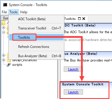
① System Console の Tools メニュー > Toolkits をクリックします。
※ すでに表示されている場合があります。
② Toolkits タブ内に、作成した名称の Toolkit が追加されています。
[Launch] ボタンをクリックします。
③ 新しいウィンドウ(タブ)として作成した Toolkit が起動し、GUI が表示されます。
④ ウィジェットを活用してデバッグを行ってください。
スクリプトのサンプル
サンプル A および サンプル B のスクリプトファイルを添付します。参考にしてください。
まとめ
Toolkit API を活用すると、FPGA の実機トラブルの問題切り分けに役立つ System Console 上でウィジェットを使用でき、さらに操作性良くデバッグすることができます。