- Semiconductor BusinessHOME
- Products and Services of Macnica,Inc.
-
technical information

-
Events and Seminars
- Handling Manufacturer
- Support
- Inquiry
- Click here to purchase products
- Semiconductor business e-mail magazine registration
![]()
![]() Narrow down by specifying conditions
Narrow down by specifying conditions
現在2189件がヒットしています。check

Intel® SoC FPGA uses U-Boot as the bootloader on the HPS (Hard Processor System) side, but you can check Ethernet communication by using the command function implemented in U-Boot. It can be used for simple tests before production software and OS/drivers are ready, such as when checking board startup.
Preparation: Setting up U-Boot
The U-Boot used does not require any special customization.
All you have to do is make the Preloader/U-Boot project generated by the BSP-Editor attached to the Intel® SoC FPGA Embedded Development Suite (SoC EDS) tool.
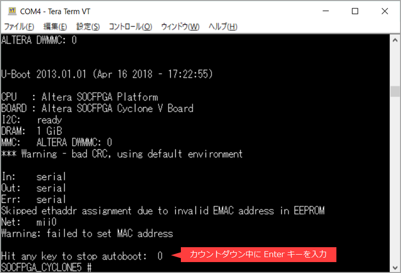
Power on the target board with the serial terminal connected.
Press Enter during the U-Boot countdown to get to the prompt waiting for commands.
This article is based on what I have tried with U-Boot on a Cyclone ® V SoC target, but the steps should be similar for other device families.
It is assumed that you already understand how to build and write U-Boot.
[Reference] SoC Beginner's Guide - How to use Preloader Generator
Environment variable setting (MAC address)
When checking Ethernet, it is necessary to set the MAC address.
If "Warning: failed to set MAC address" is displayed in the terminal log during U-Boot execution, it means that the MAC address has not been set. you save.
SOCFPGA_CYCLONE5 # setenv ethaddr 02:11:22:33:44:55 SOCFPGA_CYCLONE5 # saveenv Saving Environment to MMC... Writing to MMC(0)... doneIP address setting
Also set the IP address (ipaddr) and subnet mask (netmask) in the same way.
SOCFPGA_CYCLONE5 # setenv ipaddr 192.168.10.101 SOCFPGA_CYCLONE5 # setenv netmask 255.255.255.0*The dhcp command is also available, but it is not recommended.
Below is the log when dhcp is running for your reference.
The IP address is obtained first, but then the image is loaded. (It seems that you can get an IP address from DHCP by canceling (Ctrl + C) on the way.)
SOCFPGA_CYCLONE5 # dhcp BOOTP broadcast 1 DHCP client bound to address 192.168.10.24 *** Warning: no boot file name; using '0AD92318.img' Using mii0 device TFTP from server 0.0.0.0; our IP address is 192.168.10.24 Filename '0AD92318.img'. Load address: 0x8000 Loading: *T T T T Abortping command execution: Communication check (ICMP packet transmission/reception)
Execute the ping command with the destination IP address (eg 192.168.10.100).
For the first time, a log indicating that Linkup will be performed and the Linkup result will also be displayed.
If no response is obtained and communication fails, "ping failed; host XX.XX.XX.XX is not alive" is displayed.
SOCFPGA_CYCLONE5 # ping 192.168.10.100 Waiting for PHY auto negotiation to complete..... done ENET Speed is 1000 Mbps - FULL duplex connection Using mii0 device ping failed; host 192.168.10.100 is not aliveIf communication is successful, "host XX.XX.XX.XX is alive" will be displayed.
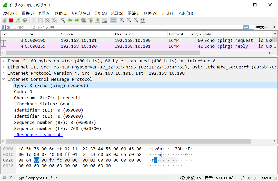
SOCFPGA_CYCLONE5 # ping 192.168.10.100 Using mii0 device host 192.168.10.100 is aliveBy using a packet monitor tool on the destination (PC) side, you can confirm that packets were actually sent and received.
(Bonus) mii, mdio commands: Read/Write of PHY register
The list of U-boot commands (displayed by the help command) seems to have Ethernet related commands besides ping.
Below is the help display for the commands mdio and mii.
<mii command HELP>
SOCFPGA_CYCLONE5 # help mii mii - MII utility commands Usage: mii device - list available devices mii device <devname> - set current device mii info <addr> - display MII PHY info mii read <addr> <reg> - read MII PHY <addr> register <reg> mii write <addr> <reg> <data> - write MII PHY <addr> register <reg> mii dump <addr> <reg> - pretty-print <addr> <reg> (0-5 only) Addr and/or reg may be ranges, e.g. 2-7.<mdio command HELP>
SOCFPGA_CYCLONE5 # help mdio mdio - MDIO utility commands Usage: mdio list - List MDIO buses mdio read <phydev> [<devad>.]<reg> - read PHY's register at <devad>.<reg> mdio write <phydev> [<devad>.]<reg> <data> - write PHY's register at <devad>.<reg> <phydev> may be: <busname> <addr> <addr> <eth name> <addr> <devad>, and <reg> may be ranges, e.g. 1-5.4-0x1f.If you are interested, please run the command and try it.
Below is the log of the result of the test run.
<mii command execution example>
SOCFPGA_CYCLONE5 # mii info 1 PHY 0x01: OUI = 0x0885, Model = 0x22, Rev = 0x02, 1000baseT, FDX SOCFPGA_CYCLONE5 # mii dump 1 0 0. (1000) -- PHY control register -- (8000:0000) 0.15 = 0 reset (4000:0000) 0.14 = 0 loopback (2040:0000) 0. 6,13 = b00 speed selection = 10 Mbps (1000:1000) 0.12 = 1 A/N enable (0800:0000) 0.11 = 0 power-down (0400:0000) 0.10 = 0 isolate (0200:0000) 0. 9 = 0 restart A/N (0100:0000) 0. 8 = 0 duplex = half (0080:0000) 0. 7 = 0 collision test enable (003f:0000) 0. 5- 0 = 0 (reserved) SOCFPGA_CYCLONE5 # mii dump 1 1 1. (796d) -- PHY status register -- (8000:0000) 1.15 = 0 100BASE-T4 able (4000:4000) 1.14 = 1 100BASE-X full duplex able (2000:2000) 1.13 = 1 100BASE-X half duplex able (1000:1000) 1.12 = 1 10 Mbps full duplex able (0800:0800) 1.11 = 1 10 Mbps half duplex able (0400:0000) 1.10 = 0 100BASE-T2 full duplex able (0200:0000) 1. 9 = 0 100BASE-T2 half duplex able (0100:0100) 1. 8 = 1 extended status (0080:0000) 1. 7 = 0 (reserved) (0040:0040) 1. 6 = 1 MF preamble suppression (0020:0020) 1. 5 = 1 A/N complete (0010:0000) 1. 4 = 0 remote fault (0008:0008) 1. 3 = 1 A/N able (0004:0004) 1. 2 = 1 link status (0002:0000) 1. 1 = 0 jabber detect (0001:0001) 1. 0 = 1 extended capabilities SOCFPGA_CYCLONE5 # mii dump 1 2 2. (0022) -- PHY ID 1 register -- (ffff:0022) 2.15- 0 = 34 OUI portion SOCFPGA_CYCLONE5 # mii dump 1 3 3. (1622) -- PHY ID 2 register -- (fc00:1400) 3.15-10 = 5 OUI portion (03f0:0220) 3. 9- 4 = 34 manufacturer part number (000f:0002) 3. 3- 0 = 2 manufacturer rev. number SOCFPGA_CYCLONE5 # mii dump 1 4 4. (01e1) -- Autonegotiation advertisement register -- (8000:0000) 4.15 = 0 next page able (4000:0000) 4.14 = 0 reserved (2000:0000) 4.13 = 0 remote fault (1000:0000) 4.12 = 0 reserved (0800:0000) 4.11 = 0 asymmetric pause (0400:0000) 4.10 = 0 pause enable (0200:0000) 4. 9 = 0 100BASE-T4 able (0100:0100) 4. 8 = 1 100BASE-TX full duplex able (0080:0080) 4. 7 = 1 100BASE-TX able (0040:0040) 4. 6 = 1 10BASE-T full duplex able (0020:0020) 4. 5 = 1 10BASE-T able (001f:0001) 4. 4- 0 = 1 selector = IEEE 802.3 SOCFPGA_CYCLONE5 # mii dump 1 5 5. (cde1) -- Autonegotiation partner abilities register -- (8000:8000) 5.15 = 1 next page able (4000:4000) 5.14 = 1 acknowledge (2000:0000) 5.13 = 0 remote fault (1000:0000) 5.12 = 0 (reserved) (0800:0800) 5.11 = 1 asymmetric pause able (0400:0400) 5.10 = 1 pause able (0200:0000) 5. 9 = 0 100BASE-T4 able (0100:0100) 5. 8 = 1 100BASE-X full duplex able (0080:0080) 5. 7 = 1 100BASE-TX able (0040:0040) 5. 6 = 1 10BASE-T full duplex able (0020:0020) 5. 5 = 1 10BASE-T able (001f:0001) 5. 4- 0 = 1 selector = IEEE 802.3 SOCFPGA_CYCLONE5 # mii dump 1 6 The MII dump command only formats the standard MII registers, 0-5. SOCFPGA_CYCLONE5 #<mdio command execution example>
 mii0
SOCFPGA_CYCLONE5 # mdio read mii0 0
Reading from bus mii0
PHY at address 1:
0 - 0x1000
SOCFPGA_CYCLONE5 # mdio read mii0 1
Reading from bus mii0
PHY at address 1:
1 - 0x796d
SOCFPGA_CYCLONE5 # mdio read mii0 2
Reading from bus mii0
PHY at address 1:
2 - 0x22
SOCFPGA_CYCLONE5 # mdio read mii0 3
Reading from bus mii0
PHY at address 1:
3 - 0x1622
SOCFPGA_CYCLONE5 #-->SOCFPGA_CYCLONE5 # mdio list mii0: 1 - Generic PHY <--> mii0 SOCFPGA_CYCLONE5 # mdio read mii0 0 Reading from bus mii0 PHY at address 1: 0 - 0x1000 SOCFPGA_CYCLONE5 # mdio read mii0 1 Reading from bus mii0 PHY at address 1: 1 - 0x796d SOCFPGA_CYCLONE5 # mdio read mii0 2 Reading from bus mii0 PHY at address 1: 2 - 0x22 SOCFPGA_CYCLONE5 # mdio read mii0 3 Reading from bus mii0 PHY at address 1: 3 - 0x1622 SOCFPGA_CYCLONE5 #
Summary
A final point to note.
The Ethernet driver implemented in U-Boot doesn't seem to listen to the receiver all the time.
Therefore, it cannot respond to pings (ICMP requests) from other terminals.
Triggered by the ping transmission from the U-Boot command, it only waits for a response from the destination terminal.
As you can see, the Ethernet program implemented in U-Boot is very simple.
With U-Boot, we recommend that you limit the test to a simple test at the level of communication confirmation, and that the details be carried out in a production software environment.
Click here for recommended articles/materials
Intel's SoC FPGA (SoC FPGA related information summary page)
SoC FPGA related articles and resources
Intel® FPGA Development Flow/FPGA Top Page