- Semiconductor BusinessHOME
- Products and Services of Macnica,Inc.
-
technical information

-
Events and Seminars
- Handling Manufacturer
- Support
- Inquiry
- Click here to purchase products
- Semiconductor business e-mail magazine registration
![]()
![]() Narrow down by specifying conditions
Narrow down by specifying conditions
現在2149件がヒットしています。check


hello.
My name is Intel F. Hanako and I provide technical support for Intel® FPGA products at Macnica.
This section introduces how to apply placement constraints to subordinate entities in Quartus® Prime Pro Edition in another project.
Notes:
・ Please refer to this article for an overview of applying placement-constrained subordinate entities to another project.
- Quartus Prime Standard Edition has different specifications and work flow. Please see this article.
Work environment
For ease of explanation, we will prepare two projects, called [Project A] and [Project B] respectively.
This flow implements the lower-level entities used in [Project A] in [Project B].
At that time, the device model number and Quartus Prime Pro Edition environment must be as follows.
|
Project A |
Project B. |
|
| FPGA |
same model number |
|
|
Quartus Prime Pro Edition |
Same version (including build number) |
|
Pro Edition partition specifications
There are two patterns for Pro Edition partition specifications.
|
type |
Overview |
| core partition | Only core resources (LUTs, registers, M20K memory blocks, and DSPs) can be included. |
| root partition | The root partition contains peripheral resources (including I/O, HSSIO, PCIe, PLL), and associated core resources, but leave the core partition open for further development. |
Both export the netlist file qdb for the partition and reuse it in another project.
Now, I will guide you through each flow in detail using the Quartus Prime Pro Edition menu.
Core partition work flow
Below is a flowchart of the process of reclaiming core partitions.
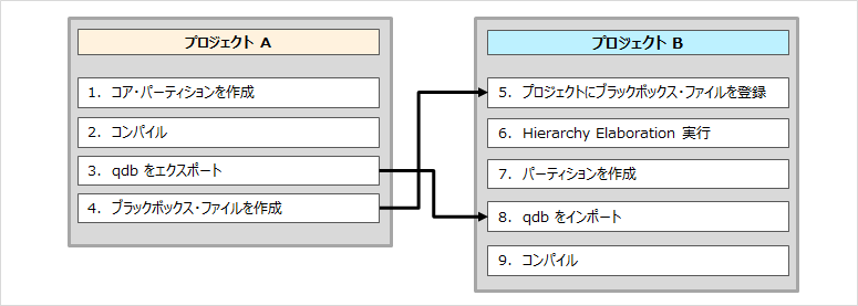
1. [Project A] Create a core partition
(1) Execute Analysis & Synthesis on the Compilation Dashboard to synthesize the design.
(2) Display the Design Partitions Window (Assignments menu) for creating partitions.
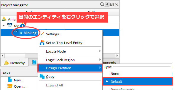
③ From the Project Navigator window, right-click on the entity for which you want to create a partition and select Design Partition > Default (in Type).
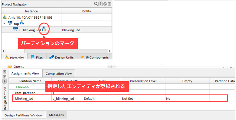
Verifies that the specified entity has been registered.
2. [Project A] Compile
Compile in the Compilation Dashboard.
3. [Project A] Export qdb
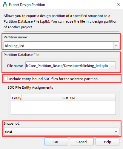
① Select Project menu > Export Design Partition.
(2) Specify each item in the Export Design Partition dialog Box.
|
item |
Overview |
| Partition name | Specify the entity you want to export from the pull-down list. |
| Partition Database File | In File name, specify the .qdb file to generate and the destination folder. (Do not change the file name.) |
| Include entity-bound SDC files for the selected partition |
You can configure whether the exported .qdb should include SDC information bound to entities. IP for Stratix® 10 targets use entity-bound SDC files by default. Arria® 10 target IP does not use entity-bound SDC files by default. To apply this option on Arria 10, first bind the .sdc to the entity in the .qsf. See the manufacturer's documentation for details. Intel® Quartus® Prime Pro Edition User Guide: Timing Analyzer : Using Entity-bound SDC Files |
| Snapshot | Choose synthesized or final. |
③ Click the OK button to generate the qdb file for the target entity in the specified folder.

Hanako's point!
If you set .qdb for Post Synthesis Export File or Post Final Export File in Design Partitions Window,
You can automate the generation of specified partitions each time you compile.
4. [Project A] Register black Box file
Create a Box file of the entities you want to export.
Be careful not to register in project A when saving the file.
example)
module blinking_led (
output [3:0] value,
input clock
);
end module
5. Register the black Box file in the [Project B] project
Open the existing project B and register the black Box file created in step 4 to the project by Add/Remove Files in Project (Project menu).
6. [Project B] Execute Hierarchy Elaboration
Perform Hierarchy Elaboration so that Quartus Prime knows the entity configuration of Project B.
7. Create a [Project B] partition
From the Project Navigator window, right-click the black Box entity and select Design Partition > Default (under Type).

8. [Project B] Import qdb
(1) Display the Design Partitions Window (Assignments menu).
(2) Double-click the Partition Database File column of the applicable partition, and use the browse button to select the file created in project A.
Specify a .qdb file.

9. [Project B] Compile
Compile in the Compilation Dashboard.
After running, check the compilation results in the compilation report to confirm that the desired partitions were applied to project B while inheriting the placement and routing from project A.
This completes the core partition work flow.
Root Partition Work Flow
Below is a flowchart of the process of reusing the root partition.
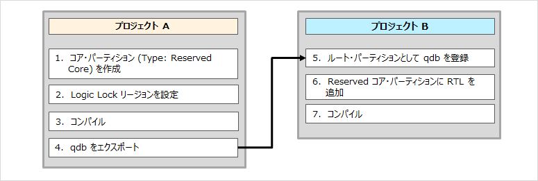
1. [Project A] Create a core partition (Type: Reserved Core)
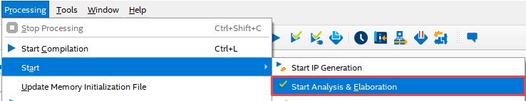
① Execute Analysis & Elaboration.
(2) Display the Design Partitions Window (Assignments menu) for creating partitions.
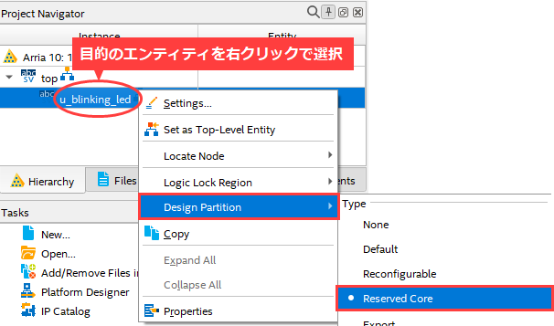
③ From the Project Navigator window, right-click the entity for which you want to create a partition, and
Select Design Partition > Reserved Core (under Type).
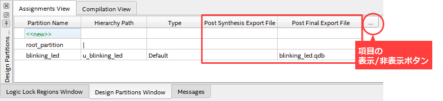
④ Generate a Post Synthesis Export File or Post Final Export File for the top entity in the Design Partitions Window
Specify a .qdb file.
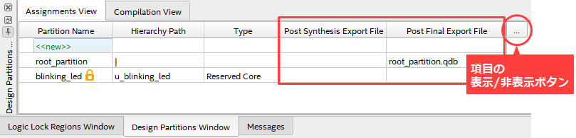
If you want to bind an SDC file to each partition, do not specify a .qdb file here,
Generate it in Export Design Partition (Project menu) after compiling.
2. [Project A] Set Logic Lock region
(1) Display the Assignments menu > Logic Lock Regions Window.
(2) In the Project Navigator window, to apply Logic Lock constraints to the core partition,
Right-click > Logic Lock Region > Select Create New Logic Lock Region.
③ Make various settings for the region.
・Origin :Arbitrary according to user specifications
・Width/Height : Arbitrary according to user specifications
・Reserved: On
・Core-Only : On
・Size/State: Fixed/Locked
・Routing Region : Select a setting other than Unconstrained according to the user's specifications.
For details on each column, please refer to "Table 2. Logic Lock Region Attributes" in this article.
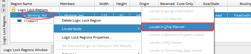
Right-click the partition in the Logic Lock Regions Window > Locate Node > Locate in Chip Planner,
Chip Planner launches.
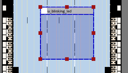
The Logic Lock area is shaded.
To save peripherals, you need to export everything outside the Lock Lock region.
3. [Project A] Compile
Compile in the Compilation Dashboard.
4. [Project A] Export qdb
Make sure the .qdb file is generated in your project folder.
If the .qdb file is not specified in step 1.(4), specify each item in the Project menu > Export Design Partition > Export Design Partition dialog Box,
Generate a .qdb file. (Please refer to the core partition work flow "Operation 3.")
5. [Project B] Register qdb as root partition
① Open the existing project B.
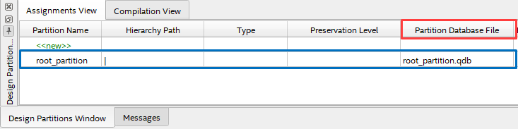
(2) Display the Design Partitions Window (Assignments menu) and double-click the Partition Database File column of root_partition.
Use the browse button to specify the .qdb file generated in project A.
6. [Project B] Add RTL to Reserved core partition
Add/Remove Files in Project (Project menu) to add the core partition RTL and all required SDC files to the project.
7. [Project B] Compile
Compile in the Compilation Dashboard.
After running, check the results of the compilation in the compilation report and see that the desired partition, while still inheriting the placement and routing in project A,
Confirm that it was applied to Project B.
This concludes the work flow for the root partition.
Click here for recommended articles/materials
How to Apply Placement Constrained Subordinate Entities to Another Project (Overview)
How to Apply Placement Constrained Subordinate Entities to Another Project (Standard Edition)
Quartus® Prime has a way to reduce compilation time
How to recompile only part of the FPGA design
Try to use incremental compilation
How to Specify the Placement of Subordinate Entities in a Design (Logic Lock)