- Semiconductor BusinessHOME
- Products and Services of Macnica,Inc.
-
technical information

-
Events and Seminars
- Handling Manufacturer
- Support
- Inquiry
- Click here to purchase products
- Semiconductor business e-mail magazine registration
![]()
![]() Narrow down by specifying conditions
Narrow down by specifying conditions
現在2168件がヒットしています。check
There are so many different products in the power supply product lineup that it can be difficult to choose one for the first time. Here, I would like to introduce the types of step-down DC/DC converters that are often used in FPGA circuit design. Let's compare the features and ease of design between linear regulators and switching regulators.
Features of step-down DC/DC converters
Step-down DC/DC converters include linear regulators and switching regulators. The characteristics of each are summarized in the table. If low noise is required and the current value is small, a linear regulator can be used. Switching regulators are used for applications that require large currents and have strict thermal design.
|
kinds |
linear regulator |
switching regulator |
|
Strong Points |
·simple ・Low noise - Few external parts |
·High efficiency |
|
Cons |
・Low efficiency ・High fever ・Poor load response |
- Loud noise |
|
Purpose |
・For analog circuits ・Low power ・Low-cost application |
・For high power logic circuits ・Applications that require low power consumption |
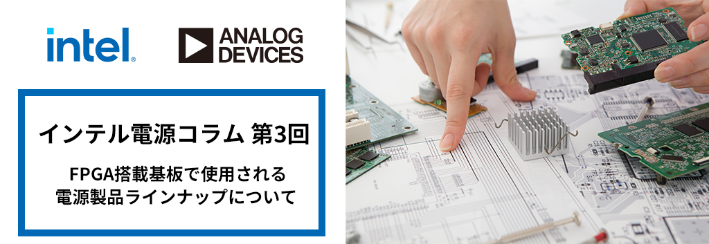
linear regulator
The most common linear regulator consists of input and output capacitors and a voltage dividing resistor that determines the output voltage, as shown in Figure 1. Since it has a very simple circuit configuration, it is relatively easy to design, so even those who have never designed a power supply circuit can do it by looking at the data sheet and selecting constants.
Also, unlike switching regulators, there is no switch operation, so there is less noise, making it ideal for circuits that dislike noise, such as analog circuits and PLL circuits.
The point to note is that heat generation increases as the difference between the input voltage and output voltage and the current increase. In particular, when creating a low voltage from a high voltage of 12V or higher, or when a current exceeding 1A is required, consider the switching regulator you choose.
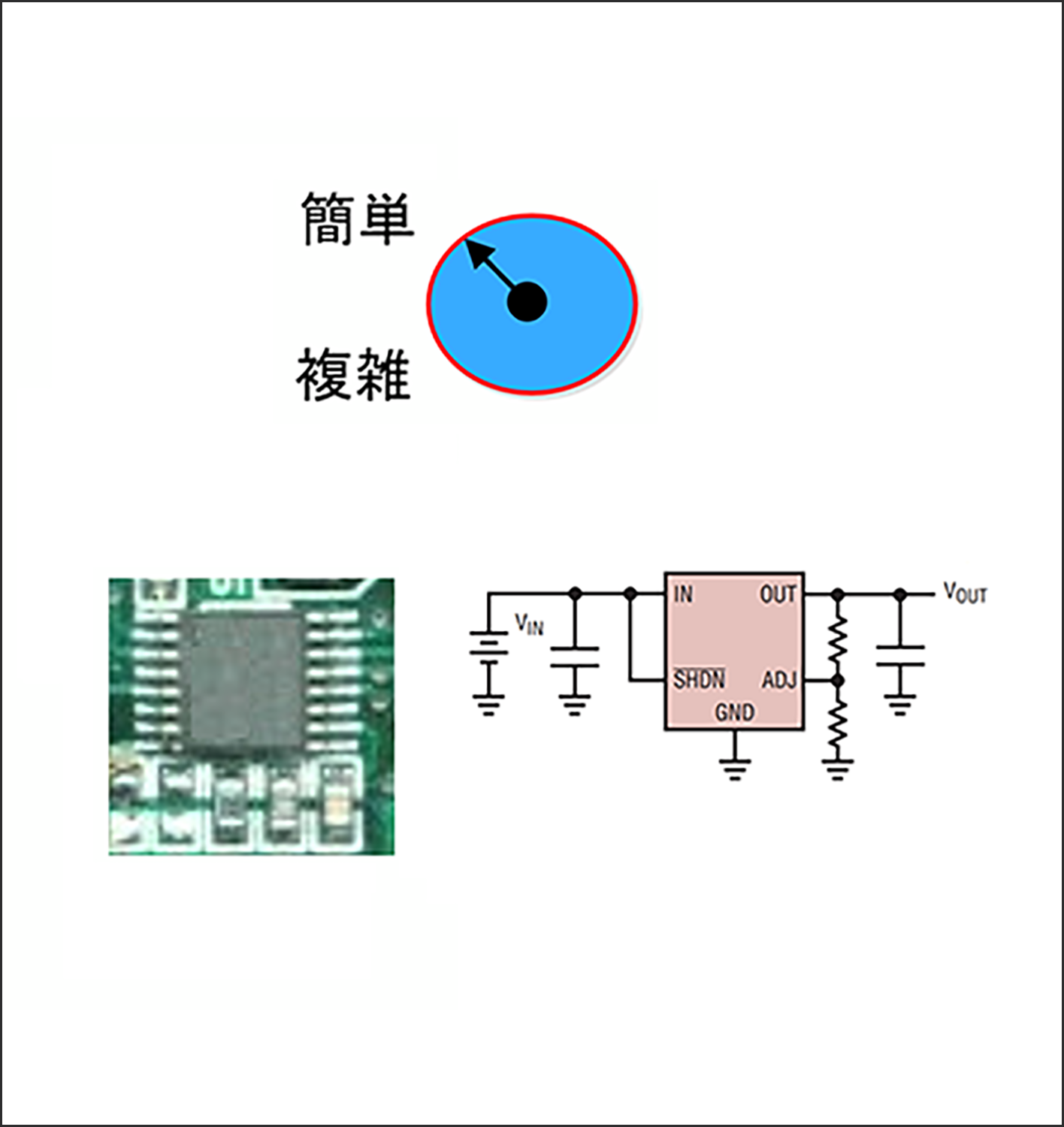
Built-in power element (monolithic) DC/DC converter
A DC/DC converter with a built-in power element has more peripheral components than a linear regulator, and requires an external inductor, and depending on the circuit type, a diode. Therefore, layout design is difficult and the difficulty level is medium.
Since it is more efficient than a linear regulator, the power that can be supplied to the FPGA is increased, and depending on the device, it is possible to supply about 10A.
However, please note that since the IC has a built-in power element, it generates a lot of heat, so if a current of 5 to 10 A is required, thermal design such as heat dissipation measures is required.
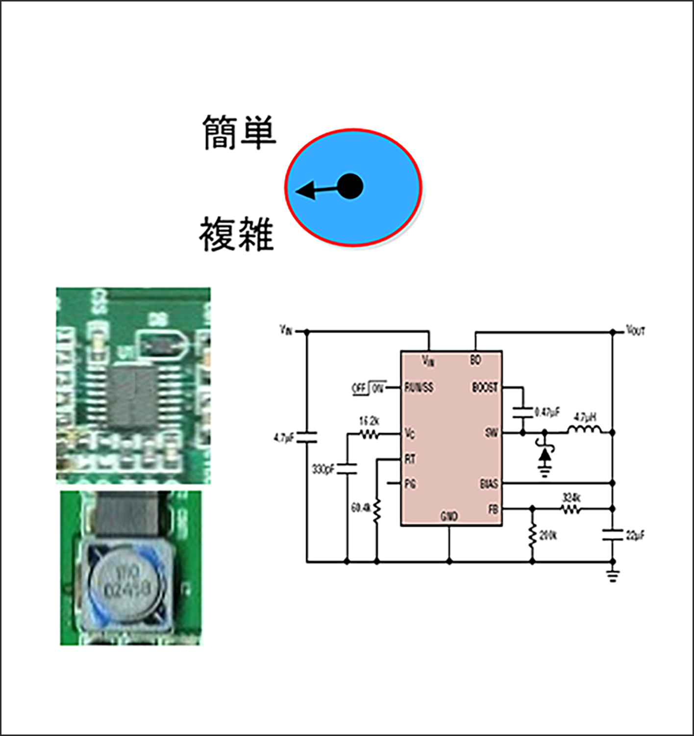
Controller type DC/DC converter
In controller type DC/DC converters, all power elements are external. This makes it possible to handle large currents by using power elements with low on-resistance and low switching loss. Additionally, since no power element is built into the small package, it is advantageous in terms of thermal design, unlike monolithic types that have built-in power elements. Used for power supply circuits of 10A to 100A or more.
However, since the power element is externally attached, many parts are used, making the layout design extremely complex. Therefore, the disadvantage is that the board area occupied by the power supply circuit becomes extremely large.
If you have no experience in designing power supply circuits, we recommend that you avoid designing high-current type power supply circuits that use controller-type DC/DC converters and instead choose a module type.
Module type DC/DC converter
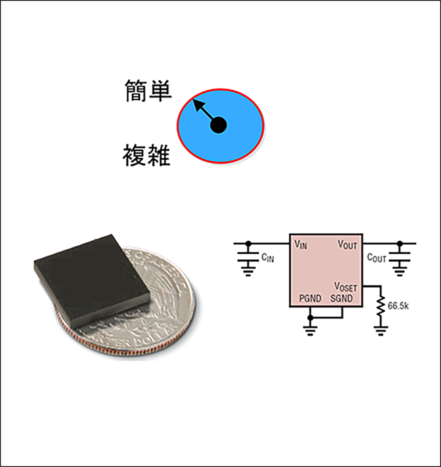
Some module type DC/DC converters can be designed using only input/output capacitors and voltage setting resistors, and can be designed in the same way as a linear regulator, making them easy to use even for those with no experience in power supply circuit design. .
A wide range of products are available, ranging from products that support currents of less than 1A to products that support currents of more than 200A, making them the perfect solution for boards equipped with FPGAs. Therefore, it is often used on Intel FPGA evaluation boards.
For multilayer boards equipped with FPGAs, it is better to use modules because the larger area of the power supply circuit leads to higher costs, and multi-phase operation using modules is effective for large currents and high-speed response. Modular products are recommended.
Summary
I explained the types of step-down DC/DC converters used on boards equipped with FPGAs. When selecting a power supply product that matches your FPGA or CPLD, please consider the characteristics of each power supply device. If you have any questions about choosing a power supply product, please feel free to contact us. We would be happy to receive support and suggestions for power supply products that are suitable for FPGAs from engineers specializing in power supply circuits.
Click here for an overview of μModule🄬 used in Intel evaluation boards>>