- 半導体事業HOME
- マクニカの製品・サービス
-
技術情報

-
イベント・セミナー
- 取扱メーカー
- サポート
- お問い合わせ
- 製品購入はこちら
- 半導体事業のメルマガ登録
![]()
![]() 条件を指定して絞り込む
条件を指定して絞り込む
現在2176件がヒットしています。check

このコラムでは「意外と知られていないけど、知っていると差がつく FPGA の技術情報」をご紹介します。
FPGA初心者の方からベテランの方まで、幅広くご活用いただける内容ですので、ぜひ最後までお付き合いください。
【第 4 回】 高精度パワーシミュレータが使われなかった理由
遅延計算に比べ、パワー計算は精度を上げるのが困難です。
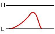
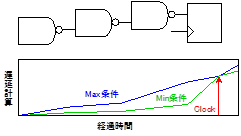
遅延計算は Min 遅延と Max 遅延で開いた誤差はクロックと同期をすることで解消されます(図1)、同期設計を推奨する理由の1つです。
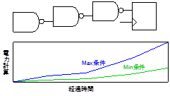
しかし消費電力の計算は、クロックが入っても、Min 電力と Max 電力の差はどんどん開いて行きます(図2)。
ではどうすればパワー計算の精度を上げることが出来るのでしょうか?
筆者は以前、以下のような機能を取り込んで、HSPICE 比で誤差数%の高精度パワーシミュレータを開発しました。
・波形傾き(Slew、Lamp)から、貫通パワーを計算する(傾きは伝搬するので遅延計算も必要です)
・DC パワーを計算する
・X パワー(論理が “X” 状態の電力)を計算する
・メモリなど特殊セルを高精度で高速計算できるモデル(アルゴリズム)を用意する
ところが筆者の期待に反し、このパワーシミュレータはあまり使われませんでした。。。
高精度のパワーシミュレータが使われなかった理由
精度の高いパワーシミュレータを使うには、回路内部の正確なトグル情報が必要です。
しかしシステムレベルのテストベンチを使ってシミュレーションする人は非常に少なく、
これが原因で、せっかく作成した高精度パワーシミュレータはお蔵入りとなってしまいました。
結局その後、入力ピンのトグル情報を入れたら回路の論理からトグル情報の伝搬を推定(入力が何回遷移したら出力が何回遷移するのか)する簡易パワーシミュレータを新たに開発し、そちらが活躍することとなりました。
パワーシミュレータの利用方法
インテル社が用意しているのは2つのパワーシミュレータです。
RTL 完成前:EPE (Early Power Estimator) で消費電力のおおまかな最大値を確認できます。
RTL 完成後:実配線容量を使ったPowerPlay Power Analyzer でより正確な電力値を確認できます。
パワーシミュレーションは誤差が大きいので、値が大きくなるようにマージンを持っています。
よって“パワーシミュレータの値だけ”でデバイス選定することはお勧めできません。
正確な電力値を知りたい時はできるだけ“実機で測定”するように心がけてください。
PowerPlay Power Analyzer が役立つのは、RTL 記述が異なる記述 A と B で消費電力の大きさを比べる時です。どちらの記述が消費電力が低いのかを知るには有効なツールです。
作成した高精度パワーシミュレータの詳細
(1)貫通パワーの計算
CMOS 回路は、止まっている時は pMOS、nMOS のどちらかのトランジスタが閉じているので、DC 電流は流れません。しかし信号が遷移している時は、少し開いた pMOS と nMOS の間を貫通電流が流れます。
ちょうど、ファミレスの2重ドアが半開きで、外から寒~い風が室内に入る感じですね。
この貫通電流を計算するためには、セルを経由する度に変化する波形の傾き値が必要です。
しかし SDF(Standard Delay Format) は波形の傾きの情報を持っていないので、別途計算しました。
(2)DC パワーの計算
第3回のコラムに書きましたが、DC パワーを計算するには、論理が ”L” 状態と “H” 状態の時間を把握する必要があります。SAIF (Switching Activity Interface format) ファイルはこの時間情報を持っていますので、そちらを参照し計算します。
DC パワーを計算しないとプルアップやプルダウンバッファの DC 電力で大きく誤差が出ますので、忘れず行う必要があります。
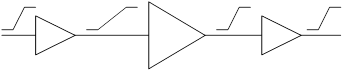
(3)X パワー/グリッジパワーの計算
X パワーは、論理が X 状態の時の消費電力です。
例えば、信号が “L” から “H” に遷移している途中で “L” に戻る時の消費電力です。
図3.では論理が “L”⇒“L” でも電力を消費します。
この消費電力は、セルの遅延時間の幅と入力信号が変化するタイミングの幅から計算できます。
論理も確認する必要があるので複雑なアルゴリズムです。
演算回路は出力が安定するまで内部でグリッジが多く発生するので、この計算をしないと誤差が大きくなります。しかしこの消費電力を計算できるツールは少ないようです。