- 半導体事業HOME
- マクニカの製品・サービス
-
技術情報

-
イベント・セミナー
- 取扱メーカー
- サポート
- お問い合わせ
- 製品購入はこちら
- 半導体事業のメルマガ登録
![]()
![]() 条件を指定して絞り込む
条件を指定して絞り込む
現在2176件がヒットしています。check
データセンターのリーフ&スパインスイッチ構成
近年、スマートフォンをはじめとするモバイルデバイスやデジタル家電の普及に伴い、通信ネットワークにおけるデータトラフィックはますます増大をしています。これに伴い、データセンターも巨大化を続け、ここに用いられる光トランシーバーの数量と伝送容量は増加の一途をたどっています。
下の図1は、現在主流となっているデータセンターのネットワーク構成の一部を模式的に表したものです。現在はリーフ(葉)&スパイン(幹)型と呼ばれる構成が主流となっています。
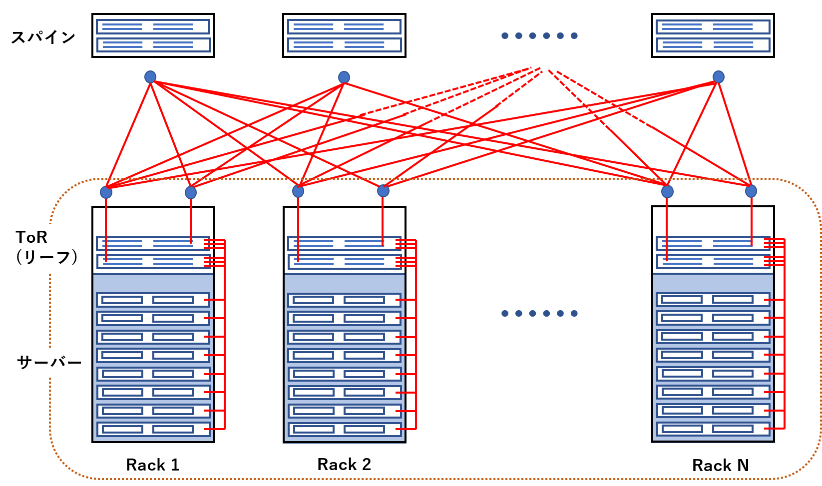
図1 リーフ&スパイン構成のスイッチ接続例
複数のサーバーが収まるラックには、これらサーバーからのデータを集約するToRスイッチ(Top of Rack、またはリーフ(葉)スイッチ)が配置されています。
このToRスイッチは、その上位に位置するルーティングスイッチ(スパイン(幹)スイッチ)と図1のようにメッシュ状に接続されるのが主流となっています。
サーバの接続ポートが不足した場合にはリーフスイッチを、スイッチング容量が不足した場合はスパインスイッチを増設すればよく、拡張性に優れた構成となっています。
光トランシーバーの下位互換性
リーフとスパインのスイッチ間の接続には、現在100Gの伝送容量を持つ光トランシーバーが多く用いられており、また次世代製品として400Gの伝送容量を持つ光トランシーバーが規格化され製品も出始めています。
スイッチを増設する場合には、メッシュ状に接続される構成上、収容できる伝送容量のアップグレードとともに既存スイッチとの下位互換性も考慮される必要があり、これらに接続される光トランシーバーについても同様のことが言えます。
下の表1は、光トランシーバーの伝送容量とフォームファクター、およびフォームファクターの下位互換性を示しています。
|
伝送容量 |
光伝送方式 |
フォームファクター |
フォームファクターの下位互換性 |
|
10G |
1x10G |
SFP+ |
- |
|
25G |
1x25G |
SFP28 |
SFP+と互換 |
|
40G |
4x10G |
QSFP+ |
- |
|
100G |
4 x 25G (SR4/LR4等) 2 x 50G (BiDi) 1 x 100G (DR/FR/LR) |
QSFP28 |
QSFP+と互換 |
|
400G |
4x100G |
QSFP56-DD |
QSFP+、QSFP28と互換 |
表1 光トランシーバーの伝送容量とフォームファクター、およびフォームファクターの下位互換性
例えば、100GのQSFP28光トランシーバーのフォームファクターは40GのQSFP+と互換であり、100Gに対応できるスイッチは40Gにも対応できるように設計されています。
また、400GのQSFP56-DD光トランシーバーのフォームファクターは、100GのQSFP28よりも電気側インターフェースのレーン数が増えていますが、下位互換性を考慮した仕様となっており、400Gに対応できるスイッチは100Gにも対応できるのが一般的です。
このように、光トランシーバーとして伝送容量はアップグレードしながらも、スイッチ間の相互接続性も考慮しています。
Breakout(ブレイクアウト)ソリューション
100Gの場合
ここで、例えば、スイッチ間の伝送容量が100Gであるネットワークで、一部のリーフスイッチだけはポートが25Gである場合を考えてみましょう。
100GBASE-SR4 QSFP28光トランシーバーは、光側インターフェースは4x25Gのパラレル伝送です。
1チャンネルあたり25Gの伝送容量がありますので、スイッチ・光トランシーバーともに4つのチャンネルを各々独立した25Gのネットワークとして扱える能力があれば、対向には4つの25GBASE-SR SFP28光トランシーバーを接続可能です。
これを100G Breakout(ブレイクアウト)といいます。
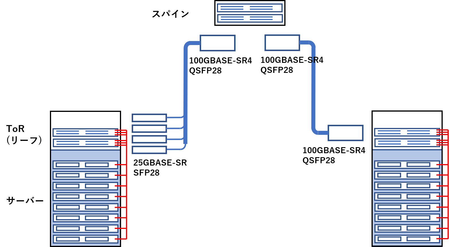
図2 100GBASE-SR4 QSFP28光トランシーバーのBreakoutソリューション例
400Gの場合
同様に、スパインスイッチのポートが400G、リーフスイッチのポートが100Gであった場合はどうでしょうか。
400GBASE-DR4 QSFP56-DD光トランシーバーはリーフ・スパイン間の接続に用いられることも想定しており、4つの100G QSFP28光トランシーバーにBreakout接続できるように考慮されています。
ただし、この場合に注意しなければならないことは、用いられる100G QSFP28トランシーバーは、上で述べたような100GBASE-SR4ではなく、100GBASE-DRである必要があります。
100GBASE-SR4と100GBASE-DRの違いは下の表2の通りです。
|
規格 |
フォームファクター |
電気側インターフェース |
光側インターフェース |
|
100GBASE-SR4 |
QSFP28 |
4x25G NRZ |
4x25G NRZ |
|
100GBASE-DR |
QSFP28 |
4x25G NRZ |
1x100G PAM4 |
表2 100GBASE-SR4と100GBASE-DR光トランシーバーの違い
400GBASE-DR4 QSFP56-DD光トランシーバーは、光側インターフェースが4x100Gとなっています。
変調方式に、それまで広く用いられてきたNRZ(Non Return to Zero)方式ではなく、PAM4(Pulse Amplitude Modulation 4:4値パルス振幅変調)を用いており、1チャンネルあたりの伝送容量を上げることで4チャンネルで400Gの伝送を可能にしています。
Breakoutアプリケーションで使用する場合は、対向の100G光トランシーバーもこのPAM4方式に対応していなくてはならず、したがって1チャンネルで100G伝送可能な光側インターフェースを持つ100GBASE-DR QSFP28光トランシーバーでなくてはならないということになります。
Broadcom社光トランシーバーのソリューション
Broadcom社では、100G Breakout、400G Breakout各々のアプリケーションに対応した光トランシーバーを量産中または開発中です。
100GBASE-SR4 QSFP28:AFBR-89CDHZ
25GBASE-SR SFP28:AFBR-735SMZ
400GBASE-DR4 QSFP56-DD:AFCT-91DRDHZ
100GBASE-DR QSFP28:AFCT-89SDHZ
この他にも多数製品ラインナップを取り揃えております。
お問い合わせ
ぜひBroadcom社トランシーバー製品ウェブサイトにお立ち寄りいただき、下記までお問い合わせください。
Broadcom メーカー情報Topへ
Broadcomメーカー情報Topページへ戻りたい方は、下記をクリックください。