- Semiconductor BusinessHOME
- Products and Services of Macnica,Inc.
-
technical information

-
Events and Seminars
- Handling Manufacturer
- Support
- Inquiry
- Click here to purchase products
- Semiconductor business e-mail magazine registration
![]()
![]() Narrow down by specifying conditions
Narrow down by specifying conditions
現在2189件がヒットしています。check
What is IBIS
IBIS stands for I/O Buffer Information Specification and is a simple representation of the input and output characteristics of a device. Since it is a "simplified expression", it is easy for device makers to request it, and it is easy for the makers to submit it. Of course, there is a limit compared to the SPICE model, but I think that it is sufficiently useful for ordinary reflection analysis.
For IBIS documentation, see:
http://www.eigroup.org/ibis/specs.htm
Terminal characteristics
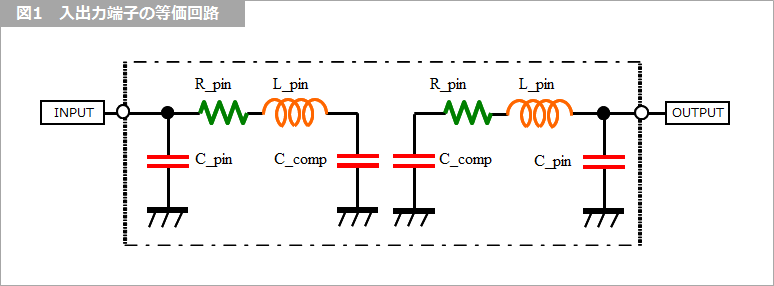
Any inductance or capacitance present at the terminals of the IC is also listed in the IBIS.
It represents the inductors and resistors of the connection parts such as the package capacitors and bonding wires shown in the equivalent circuit of Figure 1, and the capacitors of the device terminals. It may or may not have been.
Static characteristics
The values of current versus voltage are tabulated.
The IBIS specification uses the expression IV characteristics. The first column lists the voltage and the next three columns list the current typical (typ), minimum (min), and maximum (max). Standards must be specified. Separate each column with a blank (space). Tabs are allowed, but are discouraged as much as possible.
If tabs are used in the table, it is better to convert them to spaces using a text editor. The table has a minimum of 2 rows and a maximum of 100 rows.
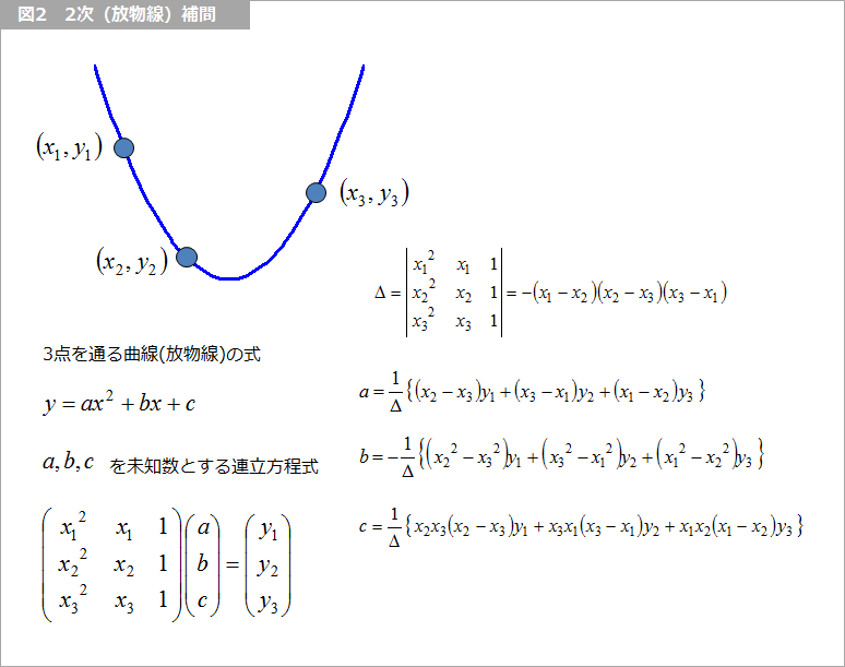
Voltage and current have a monotonically increasing (or decreasing) relationship, that is, Monotonicity. Also, the spec says to use enough data points if the curve is steep, but if there is not enough data, you can interpolate with a quadratic curve, for example. .
Figure 2 shows how to find the formula for a parabola passing through three points.
Output characteristics
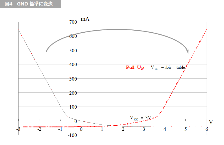
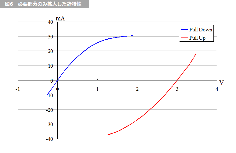
Since most CMOS devices have open inputs, we normally use only the output characteristics data, but for receivers that include termination resistors, we also use the input characteristics. Current is defined as positive when it flows into a device, but voltage is defined differently for low and high sides. The low-side characteristic (Pull-Down) expresses the voltage with respect to ground, while the high-side characteristic (Pull-Up) defines the voltage with respect to the supply voltage.
Table 1 is an excerpt from the Cyclone IV IBIS file. ttl30 stands for 3V LVTTL. Terminal attributes are usually listed near the beginning of the IBIS file. cio is the column I/O, d8 is the 8mA driver, and the last m is medium slew rate, which will be explained later. Below that, the Pulldown and Pullup data are listed.
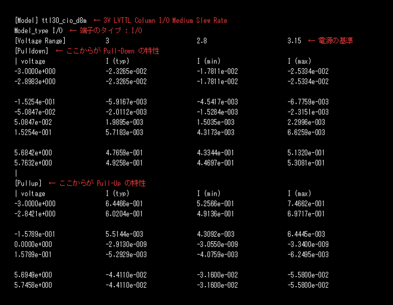
Table 1 IBIS file example
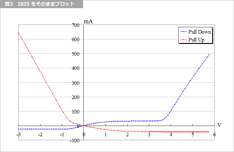
Figure 3 is a plot of this Pulldown and Pullup data, with voltage on the horizontal axis and current on the vertical axis. As it is, the pullup cannot be represented correctly, so coordinate transformation is performed as shown in Fig. 4.
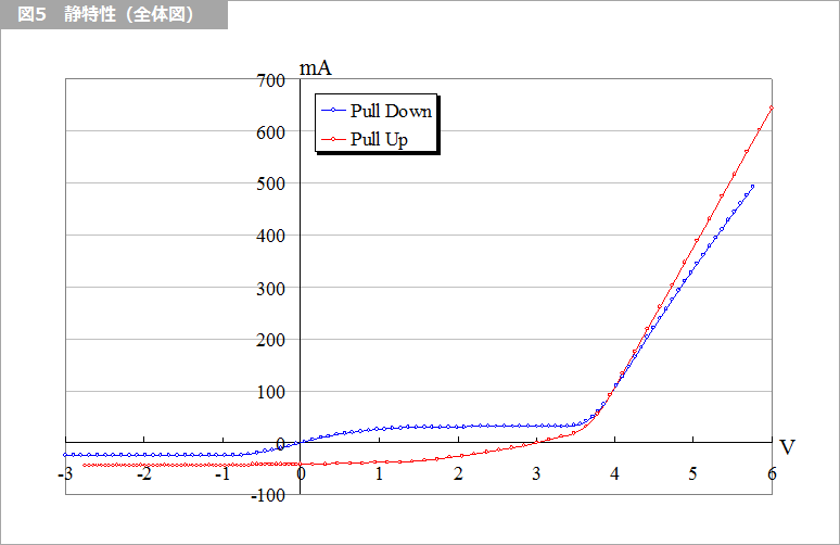
How to utilize the static characteristics obtained in this way will be described in detail in "Analysis of Reflection Using the IBIS Model - Part 2".
What is Yuzo Usui's Specialist Column?
It is a series of columns that start from the basics, include themes that you can't hear anymore, themes for beginners, and also a slightly advanced level, all will be described in as easy-to-understand terms as possible.
Maybe there are other themes that interest you!