- Semiconductor BusinessHOME
- Products and Services of Macnica,Inc.
-
technical information

-
Events and Seminars
- Handling Manufacturer
- Support
- Inquiry
- Click here to purchase products
- Semiconductor business e-mail magazine registration
![]()
![]() Narrow down by specifying conditions
Narrow down by specifying conditions
現在2168件がヒットしています。check
![[Introduction to accelerometers] Lesson 14: Let's measure angles with accelerometers (Part 2)](/business/semiconductor/articles/Article_142202_cover_1.png)
In the [Introduction to Accelerometer] series, we will explain the basic usage and application methods, focusing on analog devices' accelerometers.
In this article, we will continue to measure the angle (tilt angle) using Arduino and ADXL345. When I measured the angle last time, the ideal angle was 0° when placed horizontally, but the actual angle included a few degrees of error. I would like to remove this error.
[Introduction to accelerometer] Click here for the series list
Consider the effect of offset errors on angular measurements
previous article ([Introduction to accelerometers] Lesson 13: Let's measure the angle with an accelerometer (Part 1)) explained the principle of angle detection, but this is only an ideal situation. In general MEMS structures are Since the device has mechanical parts, the offset and sensitivity may be affected by stresses applied from the PCB, etc. during system assembly.
This time, we will consider the influence of the offset error again regarding the angle. The ADXL345 has a typical offset error of 35mg. Assuming that the acceleration change per 1° is 17.4mg, there is an error of about 2°C. There is calibration as a method to remove this error. I introduced the details earlier.[Introduction to accelerometer] Lesson 12: Let's perform offset calibration Please refer to the article for an explanation. Please also refer to the following application notes for detailed explanations.
AN-1057: Detecting Tilt with an AccelerometerImproving the accuracy of tilt measurement with an accelerometer
Try it with Arduino
We will use the accelerometer "ADXL345" and the hardware open platform "Arduino" to calculate the amount of change in gravitational acceleration and create a sample program to find the tilt angle. This time, it will be in the form of adding a calibration process to remove the offset error to the previous content.
Things to prepare
Here is what I prepared to evaluate the accelerometer this time.
・PC with Arduino IDE installed (Download Arduino IDE from From here)
・ Arduino Nano compatible board
・ Accelerometer ADXL345
・Others (USB cable (for Arduino and PC connection), breadboard, wires)
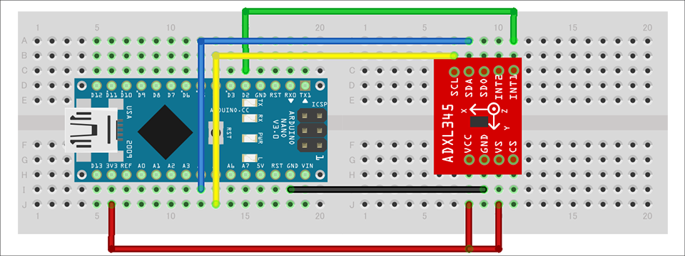
Combine the above parts to form a circuit as shown in the figure below. Power supply to Arduino Nano is supplied by USB bus power from PC. The ADXL345 supports SPI and I2C interfaces, but this time we will use the I2C interface. It also uses the INT1 pin of the interrupt pin.
Program content
In this program, the calibration process is performed once at startup, and the angle is calculated with the offset error removed. You can download the project file created with the Arduino IDE, so if you are interested, please get it from the "Document Download" below.
In this sample program, you can skip the calibration process by commenting out #define OFFSET_CALIBRATION, so you can check the effect of "Yes/No". Please try.
operation check
I checked the operation of the created program. As you can see in the video, the pitch and roll angles have an error of about 2 degrees when the device is placed horizontally. After performing the calibration process, the effect of the error is reduced, and it can be confirmed that it is closer to 0 degrees.
Thus, it is important to remove the initial offset error in angle measurement. I would like to post more articles about angle measurement, so please look forward to the next article.
Download the sample code verified this time
We provide the Arduino project file that we implemented this time. Please apply from here and give it a try.
About Accelerometer ADXL345
The ADXL345 used this time is a 3-axis digital output acceleration sensor. The main features are as follows.
・A standard accelerometer that is very easy to use with built-in ADC, operation function block, and FIFO
・Acceleration data adopts general I2C/SPI in digital serial method
・The 3-axis type sensor is a rectangular coordinate (X, Y, Z), and the acceleration acting on each axis can be obtained.
・The maximum detectable acceleration can be set in the range of 2g to 16g, and the sampling range is as wide as ~3.2kHz, so it can be applied to various applications such as impact, tilt, and motion detection.
・Flexible mode to reduce current consumption
For more information on the ADXL345, visit www.adxl345.com. data sheet Please refer to. Also, this accelerometer is very easy to use, so if you want to evaluate an accelerometer from now on, please try it on the evaluation board.
At the end
If you have any questions about the contents of this article, or if you have any problems with selecting or using accelerometers, please contact us from the following.
Analog Devices Manufacturer Information Top
If you want to return to Analog Devices Manufacturer Information Top, please click the button below.
![[Introduction to accelerometer] Thumbnail image of Let's use the interrupt function](/business/semiconductor/articles/9d56e574e3a24bcf3f076e91d90f4a53.png)