- Semiconductor BusinessHOME
- Products and Services of Macnica,Inc.
-
technical information

-
Events and Seminars
- Handling Manufacturer
- Support
- Inquiry
- Click here to purchase products
- Semiconductor business e-mail magazine registration
![]()
![]() Narrow down by specifying conditions
Narrow down by specifying conditions
現在2168件がヒットしています。check
![[Introduction to accelerometers] Lesson 11: I tried to make motion detection (Part 2)](/business/semiconductor/articles/Article_140345_cover.png)
In the [Introduction to Accelerometer] series, we will explain the basic usage and application methods, focusing on analog devices' accelerometers. This time" This is the continuation of "I tried to make motion detection (Part 1)". Last time, we created a motion for activity detection. And this time I would like to add inactivity detection motion.
[Introduction to accelerometer] Click here for the series list
Added inactivity detection function
Here, inactivity is defined as the state where "the acceleration change stays within the threshold range for a certain period of time". In other words, as shown in the figure below, if the acceleration is within the acceleration threshold range for a certain period of time, it will be inactive. By using this function together with activity detection, the range of usage of the accelerometer for motion detection is expanded. For example, as shown in the figure below, by lifting a portable device such as a mobile phone from the desk, the "boot switch function" that wakes up from the standby state is performed by active detection.In addition, it is possible to realize a "stop switch function" that automatically returns to the standby state when it is put back on the desk by inactivity detection.This time," I would like to create a "motion switch" that controls LEDs by implementing inactivity detection in "I tried to make motion detection (Part 1)".

Things to prepare
Here is what I prepared to evaluate the accelerometer this time.
・PC with Arduino IDE installed (Download Arduino IDE from here)
・ Arduino Nano compatible board
・Others (USB cable (for Arduino and PC connection), breadboard, wires)
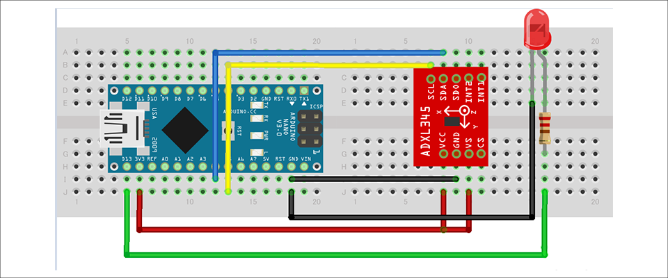
Combine the above parts to form a circuit as shown in the figure below. Power supply to Arduino Nano is supplied by USB bus power from PC. The ADXL345 supports SPI and I2C interfaces, but this time we will use the I2C interface.
Also, since the interrupt pins INT1 and INT2 are not used, they do not need to be connected this time.
Program content
"Motion detection" changes the status to active and lights the LED when the active threshold acceleration set by the user is exceeded. Also, if the acceleration change is within the inactivity threshold for a certain period of time, the status is changed from active to inactive and the LED is turned off. The following is the main flow.
(1) Obtain X, Y, and Z acceleration data at regular intervals
(2) Filter the acquired data (remove the gravitational acceleration from the acquired acceleration data)
(3) Compare the filtered data with the acceleration threshold
④ Update active/inactive status
(Active: Transition from the state where the previous acquired data does not exceed the active threshold to the active status when the latest acquired data exceeds the threshold)
(Inactive: transition from active status to inactive status when the acceleration threshold is within a certain period of time)
(5) Perform active/inactive control (LED lighting/extinguishing)
Note that this program is active/inactive detection with only the Z axis enabled.
You can download the project file created with the Arduino IDE, so if you are interested, please get it from the "Document Download" below.
operation check
Let's check the operation with the created program. From a stationary state, when a large movement was added, activity detection was performed and the LED was lit. After that, when the state without motion continued for a certain period of time, inactivity was detected and the LED was turned off. With the inactivity detection added this time, we were able to realize a "motion switch" that controls the LED.
Inactivity detection is a function that is included in the ADXL345, but I tried implementing it programmatically. Implementing it in software increases the code due to status variable management and algorithm implementation, so there are more considerations. Also, performing data processing (threshold comparison, time management, etc.) on the microcomputer side complicates power saving processing that puts the microcomputer to sleep. Therefore, I felt that the advantage of having an interrupt function on the sensor side is very large when operating on battery.
Download the sample code verified this time
We provide the Arduino project file that we implemented this time. Please apply from here and give it a try.
About Accelerometer ADXL345
The ADXL345 used this time is a 3-axis digital output acceleration sensor. The main features are as follows.
・A standard accelerometer that is very easy to use with built-in ADC, operation function block, and FIFO
・Acceleration data adopts general I2C/SPI in digital serial method
・The 3-axis type sensor is a rectangular coordinate (X, Y, Z), and the acceleration acting on each axis can be obtained.
・The maximum detectable acceleration can be set in the range of 2g to 16g, and the sampling range is as wide as ~3.2kHz, so it can be applied to various applications such as impact, tilt, and motion detection.
・Flexible mode to reduce current consumption
For more information on the ADXL345, visit www.adxl345.com. data sheet Please refer to. Also, this accelerometer is very easy to use, so if you want to evaluate an accelerometer from now on, please try it on the evaluation board.
At the end
If you have any questions about the contents of this article, or if you have any problems with selecting or using accelerometers, please contact us from the following.
Analog Devices Manufacturer Information Top
If you want to return to Analog Devices Manufacturer Information Top, please click the button below.
![[Introduction to accelerometer] Thumbnail image of Let's use the interrupt function](/business/semiconductor/articles/9d56e574e3a24bcf3f076e91d90f4a53.png)