- Semiconductor BusinessHOME
- Products and Services of Macnica,Inc.
-
technical information

-
Events and Seminars
- Handling Manufacturer
- Support
- Inquiry
- Click here to purchase products
- Semiconductor business e-mail magazine registration
![]()
![]() Narrow down by specifying conditions
Narrow down by specifying conditions
現在2171件がヒットしています。check
In the previous article Let's use LTspice - Let's add a SPICE model, we introduced how to add a part model that is not in the library.
This time, we will talk about adding a part model, which is the same as the previous article. LTspice has a function that automatically generates schematic symbols from SPICE models. This feature saves you the trouble of creating symbols from scratch and allows for quick evaluation.
If you are just starting LTspice, we recommend that you look at the "basics" from the list below.
Let's use LTspice series list is here
Also, if you would like to see a video on how to write a basic circuit and how to execute it, there is an on-demand seminar that does not require you to enter personal information, so please take a look if you are interested. Detailed information about the seminar is also provided to those who fill in the questionnaire.
LTspice On-Demand Seminar - Function check with RC circuit -
Procedure for automatic symbol generation
This time, I think that the SPICE model of the voltage reference IC that is not registered in the library was used to automatically generate the symbol.
Download the SPICE model of the 2.5V output precision voltage reference IC “REF192” from the Analog Devices website.
https://www.analog.com/jp/products/ref192.html#product-overview
Please select “SPICEModels” from the product page and download. This time, I created a working folder called "test_REF192" on the desktop of my PC and stored the files in it.
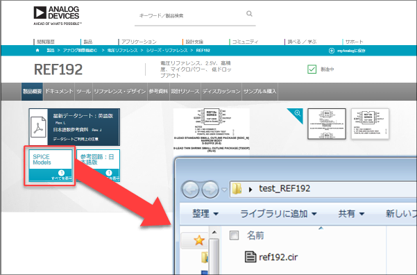
Next, open the downloaded “ref192.cir” with LTspice.
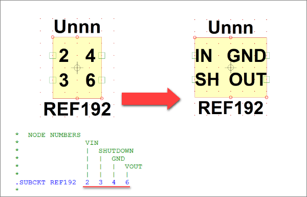
Place the cursor on the line starting with “.SUBCKT” in the netlist as shown in Figure 2, and execute “Create Symbol” from the context menu by right-clicking.
If you press "Yes (Y)" when a confirmation pop-up appears, the symbol (REF192.asy) will be created automatically.
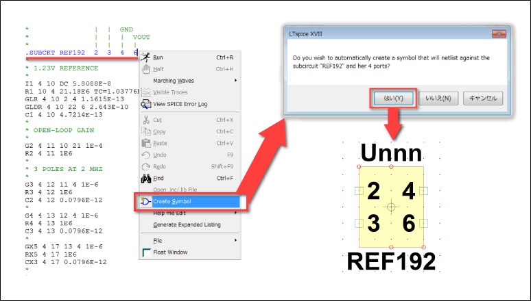
This symbol, of course, also has an internal macromodel associated with it. It is also automatically stored in the “Documents\LTspiceXVII\lib\sym\AutoGenerated” folder.
This time, I want to use the created work folder, so I saved it in the “test_REF192” folder with the “Save As” command from the File menu.
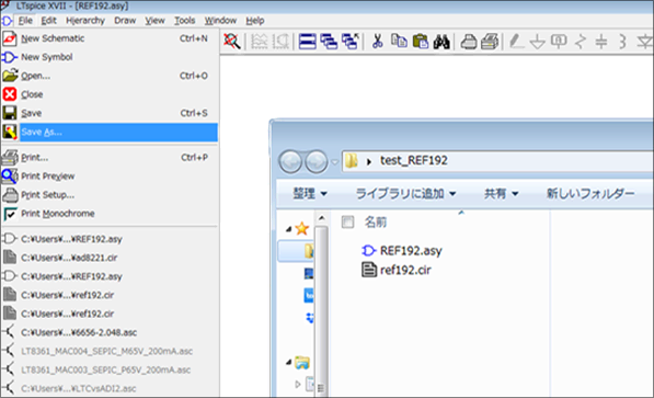
In addition, the symbol created by automatic creation assigns the terminals in the order described in the SPICE Model, and it is not visually easy to understand. Change the name of the pin in the “Symbol Editor” if necessary.
This time, the changes were made as shown in Figure 4. Also, due to the number of characters in the terminal name and the font size, the outline was made a little larger.
Create a simulation circuit
Create a simulation circuit using the created symbol.
I will draw a schematic with New Schematics, but first, name it with “Save as” and store the schematic file in the working folder of “test_REF192”. Here, the file name is “example_ref192.asc”.
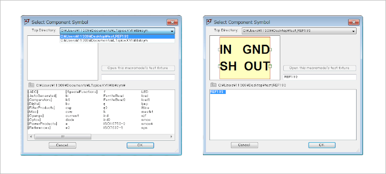
Next, read out the created REF192 symbol. Select “TopDirectory” as the working folder in the “SelectComponentSymbol” window and select “REF192” as shown below.
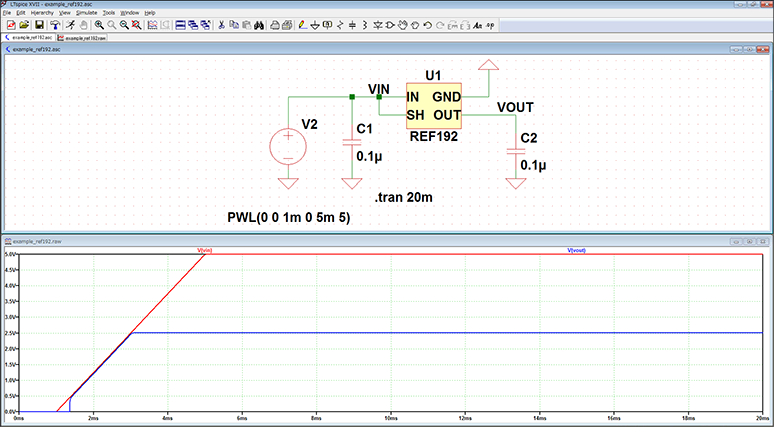
Finally, complete the schematic and run the simulation as shown below.
As shown in Figure 6, the REF192 voltage reference IC generated 2.5V from a 5V input voltage source.
LTspice demo file verified this time
The simulation file executed this time is stored. Please try!
At the end
This time, we introduced the automatic symbol generation function. When adding a new SPICE model, please use it as it is a very convenient function!
If you haven't used LTspice yet, please download LTspice from the link below!
Please try once.
We also hold regular LTspice seminars for beginners. You can learn the basic operation of LTspice, so please participate.
Click here for LTspice seminar information
Click here for recommended articles/materials
List of articles: Let's use LTspice Series
LTspice FAQ: FAQ list
List of technical articles: technical articles
Manufacturer introduction page: Analog Devices, Inc.
Click here for recommended seminars/workshops
Inquiry
If you have any questions regarding this article, please contact us below.
Analog Devices Manufacturer Information Top
If you want to return to Analog Devices Manufacturer Information Top, please click below.