- Semiconductor BusinessHOME
- Products and Services of Macnica,Inc.
-
technical information

-
Events and Seminars
- Handling Manufacturer
- Support
- Inquiry
- Click here to purchase products
- Semiconductor business e-mail magazine registration
![]()
![]() Narrow down by specifying conditions
Narrow down by specifying conditions
現在2163件がヒットしています。check

In the previous article, Let's use LTspice -Checking the operation of a DC/DC converter, we introduced the simulation function of a switching regulator using the LT8640 buck converter as an example. The following four items are listed as evaluation items for general DC/DC converters.
- Output ripple voltage
- Conversion efficiency
- Behavior at power supply startup (check for output overshoot and inrush current)
- Others (SW node waveform, output transient response, etc.)
In the previous article, we introduced how to check "1. Output ripple voltage" and "2. Conversion efficiency."
This time, I will introduce how to check "3. Behavior at power on" using LTspice.
If you are just starting LTspice, we recommend that you look at the "basics" from the list below.
Let's use LTspice series list is here
Also, if you would like to see a video on how to write a basic circuit and how to execute it, there is an on-demand seminar that does not require you to enter personal information, so please take a look if you are interested. Detailed information about the seminar is also provided to those who fill in the questionnaire.
LTspice On-Demand Seminar - Function check with RC circuit -
Behavior at power on
At power-on, the following two points must be checked.
- Output voltage overshoot
- Presence or absence of inrush current
These are included in the standard evaluation items in power supply circuit design. Each of these is a check item that cannot be removed when checking the performance of the power supply.
Specifically, overshoot of the output voltage may lead to malfunction or failure of subsequent devices.
Also, if the inrush current is large, there is a possibility that the rating of the components in the circuit (such as the inductor) will be exceeded, and this is also a problem that is directly linked to whether the power supply IC can operate normally.
For the above reasons, it is necessary to check whether there are any problems at the pre-design stage.
Now, I will introduce how to check each parameter with LTspice.
*The device and circuit used are the same as Let's use LTspice - Checking the operation of the DC/DC converter.
Overshoot of output voltage
What you see here is the output voltage waveform at power-up.
The point is to check the output voltage waveform at the minimum and maximum values of the input voltage of the required specifications, not just one condition. Similarly, for the load current, it is necessary to change the conditions from the minimum value to the maximum value of the load current of the required specifications and check.
Observation points should be checked not only for overshoot, but also for ringing and undershoot.
If these occur, not only will it take longer than necessary for the output voltage to stabilize, but if the fluctuation is large, it will lead to malfunction or failure of subsequent devices (microcomputers, FPGAs, etc.).
Confirmation of output voltage waveform (during normal operation)
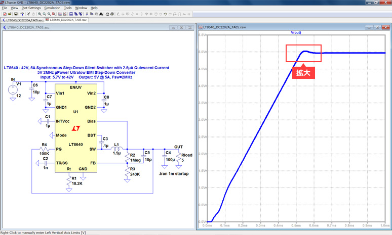
First, let's look at the output voltage waveform in the normal state.
Zoom in on the overshoot and check the peak voltage.
This time, we will expand the range from 500 μs to 700 μs, including the steady state.
*For the waveform enlargement procedure, refer to Let's use LTspice -Checking the operation of the DC/DC converter.
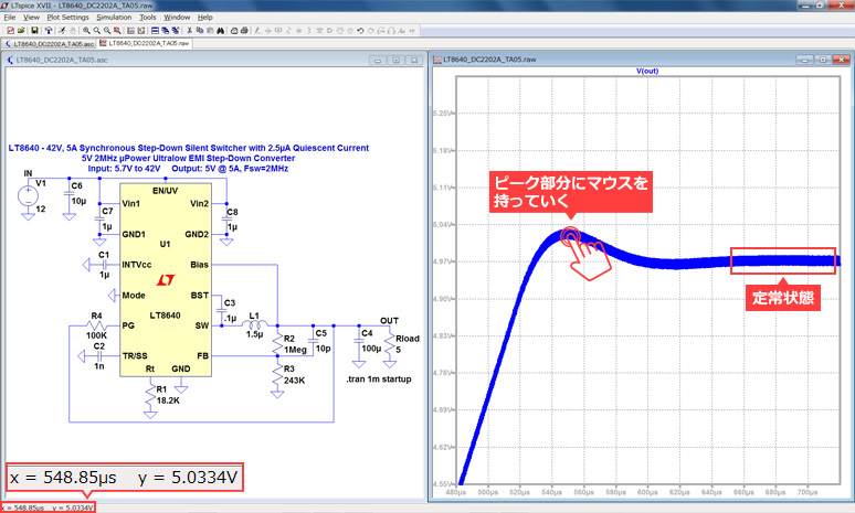
If you move the mouse to the approximate peak, you will see 5.0334V at the bottom left of the screen.
Since the output voltage (at steady state) is 5V, there is no problem in most cases (error of about 0.7% against the output voltage).
Click the Autorange button if you need to find peak values for details.
*For the Autorange button, refer to Let's use LTspice -Checking the operation of the DC/DC converter.
This time, we introduced how to check the output voltage overshoot using normal operation as an example.
Ringing, overshoot, and undershoot occur significantly in abnormal conditions. To improve the abnormal state, it is possible to take measures by adjusting the phase/gain margin, soft start, and adjusting the capacity of the output capacitor.
Confirmation of output voltage waveform (at the time of abnormal operation)
Next is the case of an abnormality.
The abnormal state mentioned here is, for example, when the overshoot voltage reaches the absolute maximum rating of the subsequent device.
Here, I would like to change the capacitance of the capacitor connected to the soft start pin in the LT8640, simulate it, and create an abnormal state.
[Supplement] Soft start is used to control the rate at which the output voltage rises at startup.
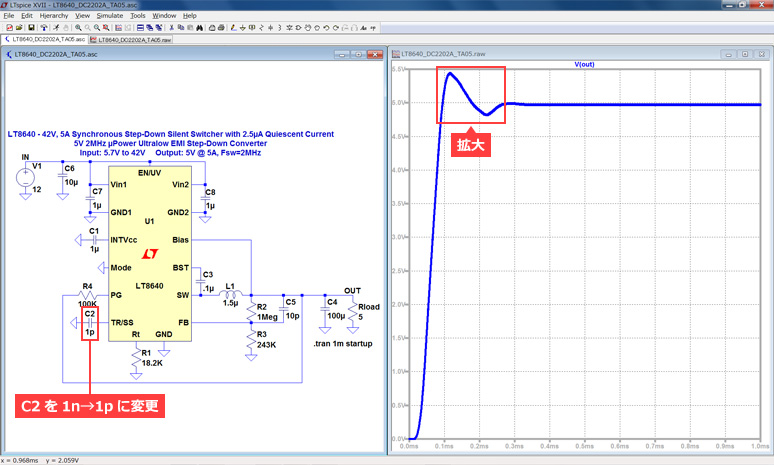
The above is the result of simulating by changing the constant of the soft-start capacitor (C2) connected to the TR/SS pin in the circuit diagram from 1nF to 1pF. If you zoom in on the overshoot, you can clearly see the difference.
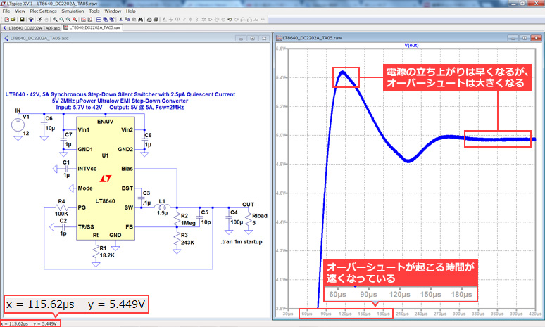
Compared to normal, the peak voltage is 5.449V, which is an error of about 9% with respect to the output voltage of 5V.
For example, if the voltage accuracy required by the CPU is within 5%, it will be judged as abnormal and the power supply circuit will need to be reviewed.
In this way, with LTspice, you can easily confirm that the characteristics change greatly with one soft start capacitor.
[Addition 1] Analysis by Step command
This time, in the simulation of the output voltage overshoot, we changed the constants in the circuit and compared the respective waveform results to confirm the difference. Wouldn't it be convenient if the output voltage results from changing constants in the circuit could be displayed on the same screen?
In LTspice, it can be realized by using the analysis function using the Step command. Here, we will introduce how to set the analysis using the Step command.
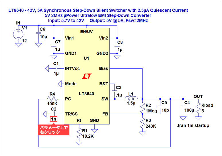
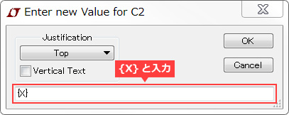
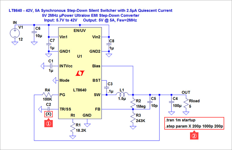
1. Assign a symbol to the part you want to step change.
This time, assign the symbol {X} to C2 (soft start capacitor).
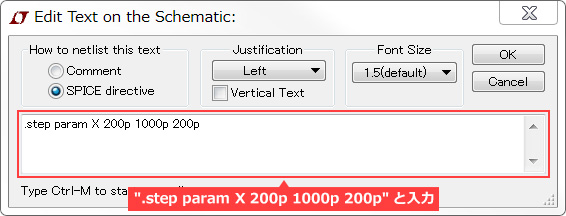
2. Click ".op" in the toolbar to set the command.
Enter ".step param X 200p 1000p 200p" in "Edit Text on the Schematic".
This means changing the value of the capacitor (C2) from 200p to 1000p in 200p steps.
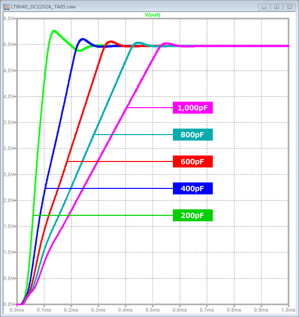
3. Press the Run button.
On the result screen, you can check the output waveform when changing the value of C2 in 5 patterns on the same screen.
It can be seen that the smaller the value of C2, the faster the power rise and the larger the overshoot.
Presence or absence of large inrush current
Next, check for excessive inrush current.
When the power supply is started, a rush current flows when the output voltage rises.
If this current is too large, the supply current from the preceding power supply circuit or battery that supplies power will be in an overcurrent state, causing a voltage drop, and in the worst case, the power supply that is supplying power will shut down. may be connected.
Of course, there is also the possibility that the ratings of components in the circuit (such as inductors) may be exceeded, and in that case normal operation as a power supply circuit will not be possible.
Confirmation of inductor current waveform
Here, the measurement of the inductor current is explained as an example.
The circuit is the same as the one used when checking the overshoot of the output voltage. Execute the Step command analysis (C2 capacitor) to display the inductor current measurement result.
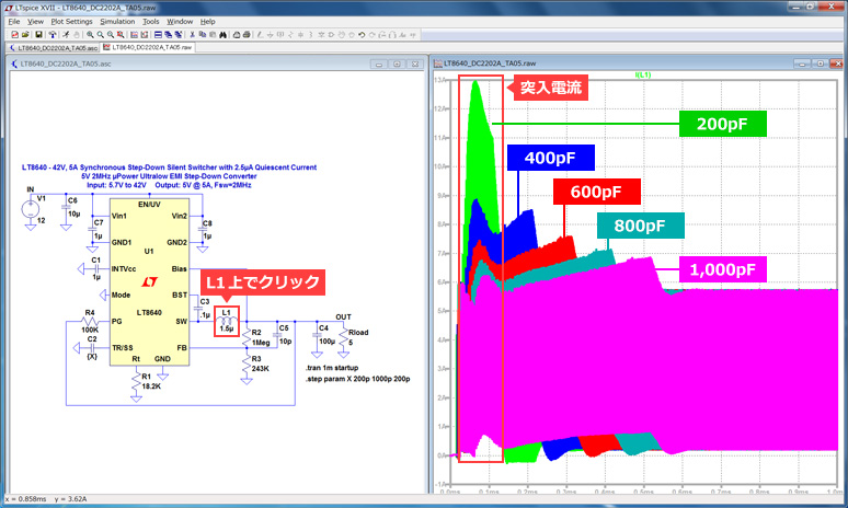
A mouse click on L1 shows the inductor current.
The part framed in red is the inrush current. When C2=200pF, a current of 13A is temporarily flowing.
In this case as well, we found that the smaller the value of C2 (soft start capacitor), the larger the inrush current.
When selecting an inductor, it is necessary to select it so that there are no problems with the specifications, including this inrush current.
[Addition 2] How to divide the plot frame
Let's use LTspice - In the output result waveform of "LT8640 circuit diagram and input / output waveform" of DC / DC converter operation check, the input voltage (Vin) and the output voltage (Vout) are plotted in separate graphs. Did you notice that?
If you can actually see the current and voltage waveforms on a separate screen, I think it will lead to an increase in work efficiency.
Below are the steps.
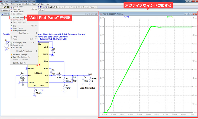
1. To separate plot panes, select "Add Plot Pane" from the "Plot Settings" pull-down menu.
*Please note that the Plot Settings pull-down menu will not appear unless the waveform screen is the active window.
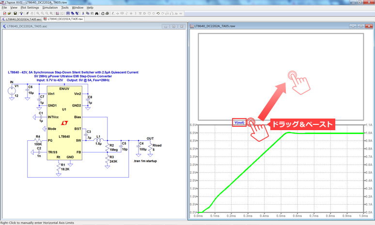
2. A new plot pane will appear at the top of the waveform window.
Drag the title of the waveform you want to move (Vout here) to the new plot frame.
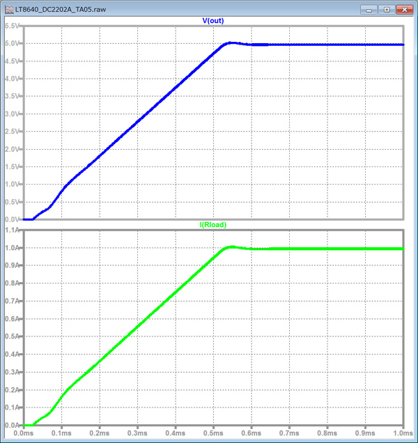
3. The Vout waveform is displayed in the upper half of the screen, and the Iout waveform is displayed in the lower half of the screen.
If you want to add more new plot frames, return to step 1 and repeat the same operation to increase the number of plot frames to 3, 4, and so on.
Also, when you want to delete a waveform, select the scissors mark (Cut) on the toolbar and click the mouse on the name of the waveform you want to delete.
Waveforms can be deleted. Similarly, if you want to delete the plot frame, select Cut and click the mouse.
At the end
Continuing from the last time, I introduced how to check the characteristics of a DC/DC converter using LTspice.
This time, we focused on the power supply start-up, but it can be used to check a wide variety of other characteristics.
We will continue to introduce various functions in the future, so please continue to support us.
Various LTspice seminars are also held regularly. You can learn the basic operation of LTspice, so we lookforward to your participation.
Click here for LTspice seminar information
Click here for recommended articles/materials
LTspice List of articles: Let's use LTspice series
LTspice FAQ: FAQ list
List of technical articles: technical articles
Manufacturer introduction page: Analog Devices, Inc.
Click here for recommended seminars/workshops
Inquiry
If you have any questions regarding this article, please contact us below.
Analog Devices Manufacturer Information Top
To return to the Analog Devices manufacturer information top page, please click below.